Valve Symbols For Drawings
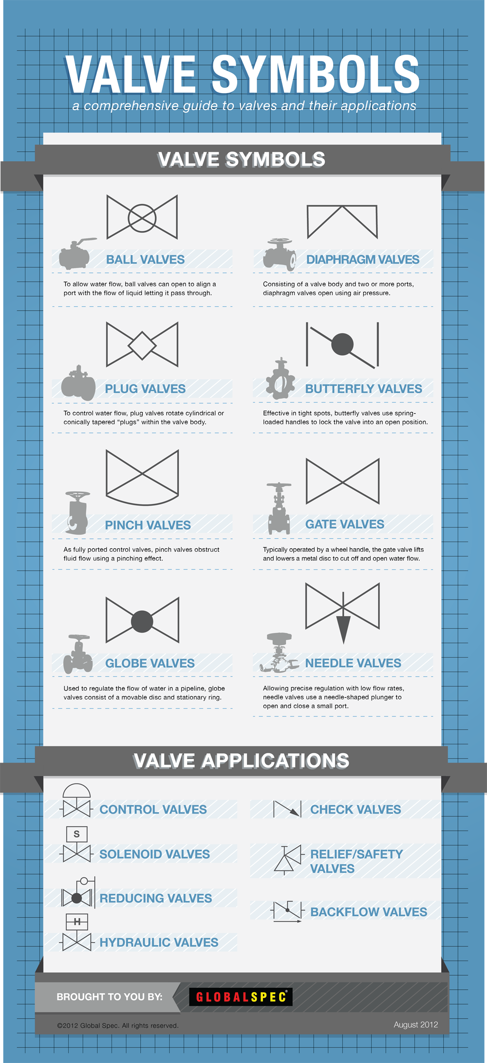
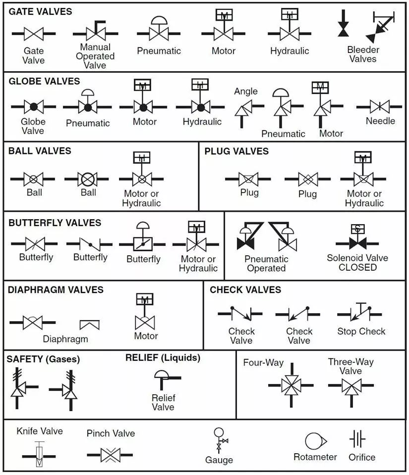
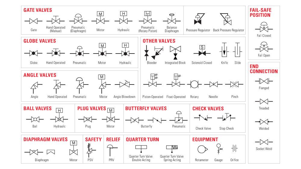
Valve Symbols For Drawings - The symbols for these components aren’t drawn to scale and aren’t intended to be dimensionally accurate. Valve symbols are used to signify the pressure, flow and direction of fluids through a valve. Knowing your valve symbols will make your life much easier when it comes time to decipher your pipe and system diagram. Valve types per category and their symbols. Engineers use control valve symbols to identify the type of control valve they want to specify for a given application. Figure 1 shows the symbols that depict the major valve types. The instruments’ function within a process. Slide a flat, cylindrical, or spherical surface across an orifice (for example, gate and plug valves). In such cases, information concerning the valve type may be conveyed by the component These valve symbols convey essential information about the valve type, function, and operation, facilitating effective communication among engineers, designers, and technicians. The complex world of process and instrumentation drawings (p&ids) is replete with a range of valve diagrams and symbols. These valve symbols convey essential information about the valve type, function, and operation, facilitating effective communication among engineers, designers, and technicians. Rotate a disc or ellipse about a shaft extending across the diameter of an orifice (for example, a butterfly or. Web in each process and instrumentation diagram, valves have specific symbols that make them easy to recognize. The symbol typically consists of the actual valve symbol, and the actuation method such as pneumatic, hydraulic, or electric. Web to accurately represent these valves in drawings and schematics, a standardized set of symbols is employed. To read and understand engineering fluid diagrams. Web p&ids include standard symbols that explain: These valve symbols convey essential information about the valve type, function, and operation, facilitating effective communication among engineers, designers, and technicians. A comprehensive guide to understanding different types is meticulously crafted to serve as an indispensable resource for industry professionals seeking to navigate the complexities of valve identification and application with unwavering confidence.. Downloadable pdf of valve, actuator and other popular p&id symbols. Web valve symbols valves are used to control the direction, flow rate, and pressure of fluids. These cad blocks have been drafted in autocad 2021 software. Web what are valve symbols and why are they important in engineering drawings? Web isometric drawing symbols for piping valves. It should be noted that globe and gate valves will often be depicted by the same valve symbol. Web move a disc, or plug into or against an orifice (for example, globe or needle type valve). In such cases, information concerning the valve type may be conveyed by the component What does piping & instrumentation diagram (p& id) imply? Try. How do i read valve symbols and p&id diagrams? What does piping & instrumentation diagram (p& id) imply? Try these free dwg files for your plumbing and mechanical drafting of piping and instrumentation diagram. Get tailored plant training courses. Web to accurately represent these valves in drawings and schematics, a standardized set of symbols is employed. What does piping & instrumentation diagram (p& id) imply? The symbols for these components aren’t drawn to scale and aren’t intended to be dimensionally accurate. What is a piping & instrumentation diagram (p&id)? Valve symbols are used to signify the pressure, flow and direction of fluids through a valve. How do i read valve symbols and p&id diagrams? Web in each process and instrumentation diagram, valves have specific symbols that make them easy to recognize. Web valve symbols in process and instrumentation diagrams. What common symbols are included? Web what are valve symbols and how are they used? Web here is a list of symbols for various types of valves used in process industry. Web valve symbols in process and instrumentation diagrams. These valve symbols convey essential information about the valve type, function, and operation, facilitating effective communication among engineers, designers, and technicians. Web construction drawing symbols ensure that construction documents are clear, concise and universally interpretable, facilitating global collaboration and contributing to the efficiency and success of construction projects. These symbols are standardized. Valve symbols are used to signify the pressure, flow and direction of fluids through a valve. Web so, to understand a system shown on a process flow diagram (fd) or a piping and instrument diagram (p&id), you must understand the valve symbols. In this article, we will identify the most commonly used control valve symbols. Web a piping and instrumentation. Flow control and fluid transfer. Web for my p&id drafting of valves, what industry standard symbols should i use? While each of these symbols has several variables for their different types of valves, these main category symbols will help get a general understanding. Web here is a list of symbols for various types of valves used in process industry. Figure 1 shows the symbols that depict the major valve types. Slide a flat, cylindrical, or spherical surface across an orifice (for example, gate and plug valves). Web construction drawing symbols ensure that construction documents are clear, concise and universally interpretable, facilitating global collaboration and contributing to the efficiency and success of construction projects. Engineers use control valve symbols to identify the type of control valve they want to specify for a given application. The instruments’ function within a process. Downloadable pdf of valve, actuator and other popular p&id symbols. In such cases, information concerning the valve type may be conveyed by the component The significance of valve symbols A comprehensive guide to understanding different types is meticulously crafted to serve as an indispensable resource for industry professionals seeking to navigate the complexities of valve identification and application with unwavering confidence. The symbol typically consists of the actual valve symbol, and the actuation method such as pneumatic, hydraulic, or electric. Knowing your valve symbols will make your life much easier when it comes time to decipher your pipe and system diagram. Valves are used to control the direction, flow rate, and pressure of fluids.
Valve Symbols Free CAD Block And AutoCAD Drawing

Valve Symbols 101 A Comprehensive Guide
Valve symbols

check valve symbols on drawings Symbols engineering process diagram
Valve Symbols

Valve Symbols in P&ID Ball Valve, Relief Valve and more

Drawing Symbol for Valves and Joints Engineer Diary
Valve Symbols for P&IDs The Engineering Concepts

Types Of Valves, Their Functions And Symbols Engineering Discoveries
The Most Common Control Valve Symbols on a P&ID Kimray
To Read And Understand Engineering Fluid Diagrams And Prints, Usually Referred To As P&Ids, An Individual Must Be Familiar With The Basic Symbols.
Web Valve Symbols Valves Are Used To Control The Direction, Flow Rate, And Pressure Of Fluids.
Valve Symbols Are Graphical Representations Of Various Types Of Valves Used In Piping And Instrumentation Diagrams (P&Ids) And Other Engineering Schematics.
The Process Flow Diagram (Pfd), Which Explains A Relatively Typical Flow Of Plant Processes About Significant Equipment Of A Plant Facility, And The Piping And Instrumentation Diagram Have A.
Related Post: