Technical Drawing Symbols
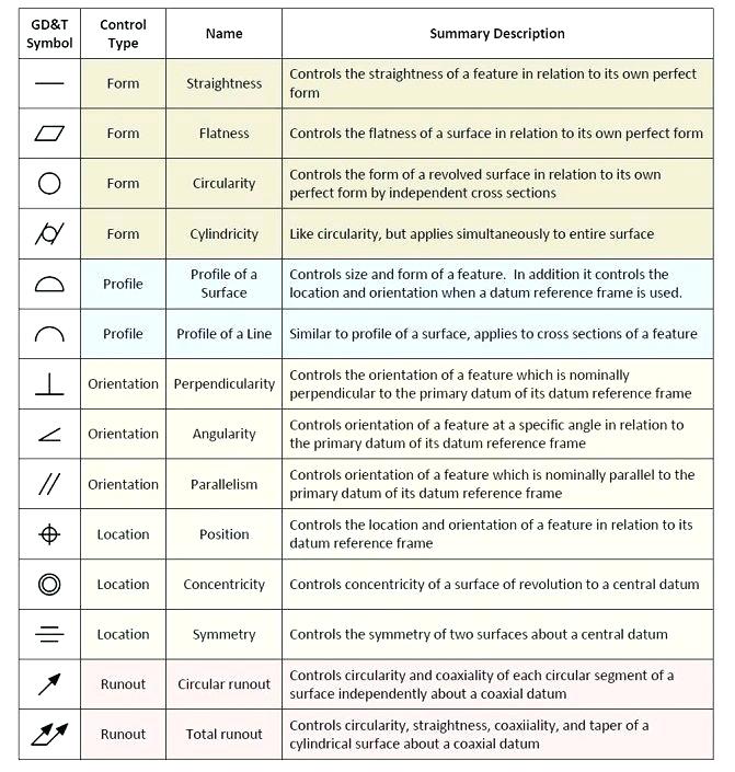
Technical Drawing Symbols - If you’re studying engineering and need a reference sheet for these drafting symbols, you’ve come to the right place. Web engineering drawing abbreviations and symbols are used to communicate and detail the characteristics of an engineering drawing. Form, orientation, location, and runout. The purpose of this guide is to give you the basics of engineering sketching and drawing. You can also check out the gd&t symbols and terms on our site. Symbols provide a “common language” for drafters all over the world. We offer you our tips which we believe are useful for dispelling uncertainty by comparing the symbol with its graphic representation. Web understanding the symbols and conventions used in technical drawings is key to creating accurate designs. The need for precise communication in the preparation of a functional document distinguishes technical drawing from. The representation of the object in figure 2 is called an isometric drawing. True position theory (size value in rectangular frame) Form, orientation, location, and runout. Web to use technical drawings effectively, specialist knowledge is required to understand the symbols, rules, and standards used. Web iso 15786:2008 (en) technical drawings — simplified representation and dimensioning of holes. This list includes abbreviations common to the vocabulary of people who work with engineering drawings in. Web engineering drawing abbreviations are a set of standardized symbols and abbreviations used on engineering drawings to represent common terms and phrases. You can also check out the gd&t symbols and terms on our site. One of the best ways to communicate one’s ideas is through some form of picture or drawing. This part of iso 129 establishes the general. If you’re studying engineering and need a reference sheet for these drafting symbols, you’ve come to the right place. But they do not provide the information that technical drawings give you. Web to use technical drawings effectively, specialist knowledge is required to understand the symbols, rules, and standards used. Web iso 15786:2008 (en) technical drawings — simplified representation and dimensioning. We offer you our tips which we believe are useful for dispelling uncertainty by comparing the symbol with its graphic representation. Web this document gives general rules for the execution of technical drawings (2d and 3d), as well as presenting the structure of the other parts of the iso 128 series. True position theory (size value in rectangular frame) Knowing. “sketching” generally means freehand drawing. From line types that identify different parts of your design, to lettering styles that provide information about dimensions and other specifications, there are a few essential aspects you must understand when interpreting technical drawings. Web standard symbols for mechanical components use such shapes as circles, ovals, arcs, triangles, squares, rectangles, polygons, lines, arrows, and other. Web basic types of symbols used in engineering drawings are countersink, counterbore, spotface, depth, radius, and diameter. Web many of the symbols and principles of technical drawing are codified in an international standard called iso 128. Web iso 15786:2008 (en) technical drawings — simplified representation and dimensioning of holes. We offer you our tips which we believe are useful for. This list includes abbreviations common to the vocabulary of people who work with engineering drawings in the manufacture and inspection of parts and assemblies. Classification and symbols of geometric tolerance characteristics. This is especially true for the engineer. This part of iso 129 establishes the general principles of dimensioning applicable for all types of technical drawings. Web this document gives. Web this document gives general rules for the execution of technical drawings (2d and 3d), as well as presenting the structure of the other parts of the iso 128 series. What are the types of technical drawings? This list includes abbreviations common to the vocabulary of people who work with engineering drawings in the manufacture and inspection of parts and. Web engineering drawing abbreviations and symbols are used to communicate and detail the characteristics of an engineering drawing. We offer you our tips which we believe are useful for dispelling uncertainty by comparing the symbol with its graphic representation. Web the asme y14.5 standard establishes symbols, definitions, and rules for geometric dimensioning and tolerancing. Note the figures in this part. Web the asme y14.5 standard establishes symbols, definitions, and rules for geometric dimensioning and tolerancing. Web gd&t drawings and symbols. However, symbols can be meaningful only if they are created according to the relevant standards or conventions. Web this chapter covers all of the major gd&t tools for engineering drawings including dimensions, tolerances, gd&t symbols, datums, feature control frames and. “sketching” generally means freehand drawing. Geometric tolerances are specified using symbols on a drawing. Web engineering drawing abbreviations are a set of standardized symbols and abbreviations used on engineering drawings to represent common terms and phrases. We will treat “sketching” and “drawing” as one. But they do not provide the information that technical drawings give you. You can also check out the gd&t symbols and terms on our site. Web there are 12 geometric tolerancing characteristics with the corresponding symbols shown. The purpose of this guide is to give you the basics of engineering sketching and drawing. Currently, we have 16 symbols for geometric tolerances, which are categorized according to the tolerance they specify. The characteristics are grouped into four types of tolerance: The need for precise communication in the preparation of a functional document distinguishes technical drawing from. Web iso 15786:2008 (en) technical drawings — simplified representation and dimensioning of holes. Web engineering drawing abbreviations and symbols are used to communicate and detail the characteristics of an engineering drawing. Data and information in drawings. The representation of the object in figure 2 is called an isometric drawing. Here are more commonly used engineering drawing symbols and design elements as below.
Engineering Drawing Symbols And Their Meanings Pdf at PaintingValley

Civil Engineering Drawing Symbols And Their Meanings at PaintingValley

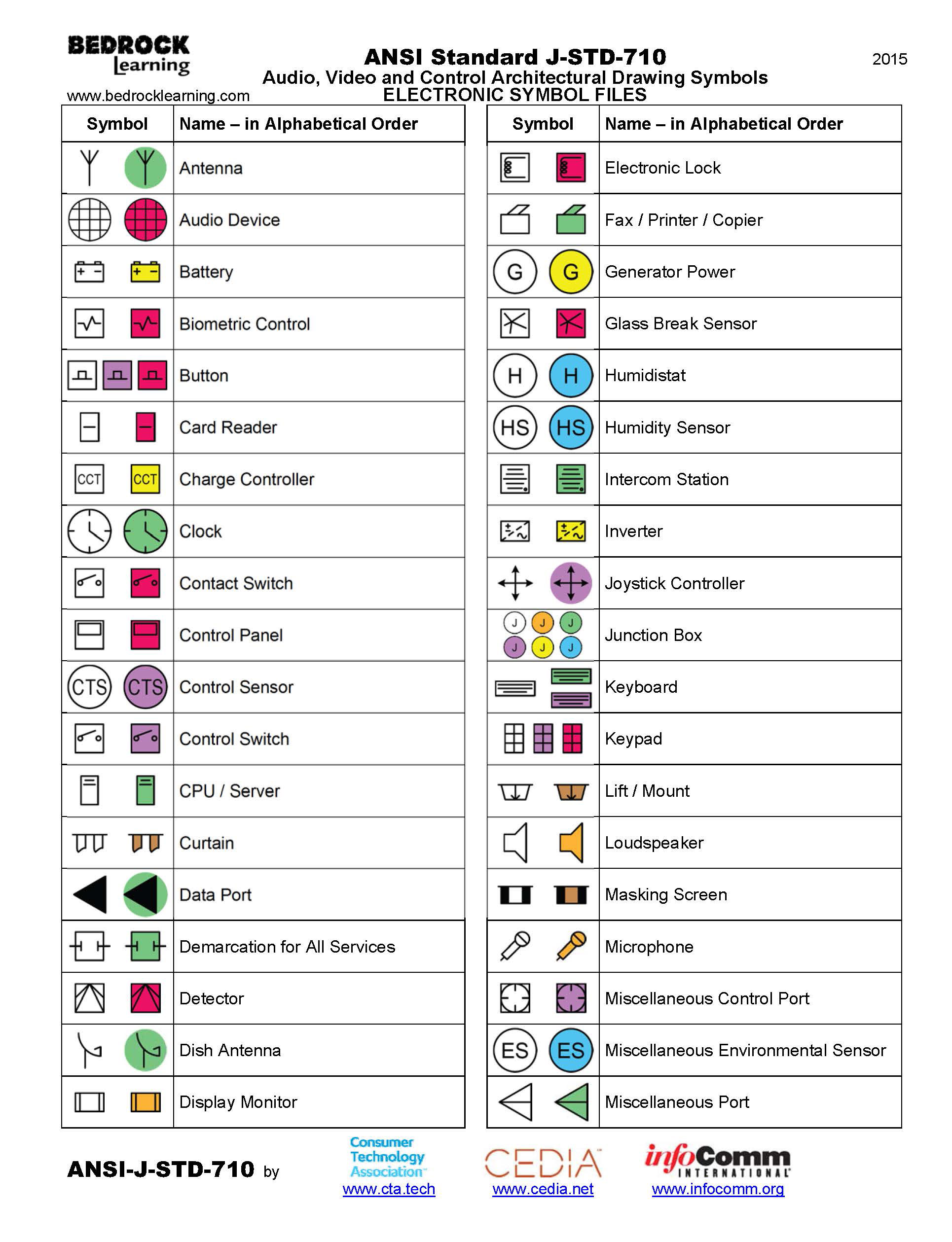
ANSI Standard JSTD710 Architectural Drawing Symbols Bedrock Learning

Engineering Drawing Symbols And Their Meanings Pdf at PaintingValley

Mechanical Engineering Drawing Symbols Pdf Free Download at
Architectural Drawing Symbols Free Download at GetDrawings Free download

Engineering Drawing Symbols And Their Meanings Pdf at PaintingValley

Mechanical Drawing Symbols Mathematics Symbols Process Flow Diagram

Mechanical Engineering Drawing Symbols Pdf Free Download at
Engineering Drawing Symbols And Their Meanings Pdf at PaintingValley
Web To Use Technical Drawings Effectively, Specialist Knowledge Is Required To Understand The Symbols, Rules, And Standards Used.
Web Identifying Symbols And Notations:
This Part Of Iso 129 Establishes The General Principles Of Dimensioning Applicable For All Types Of Technical Drawings.
What Are The Types Of Technical Drawings?
Related Post: