Phantom Lines In Engineering Drawing
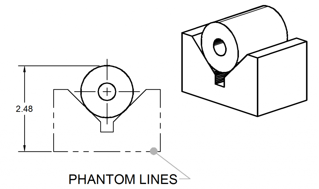
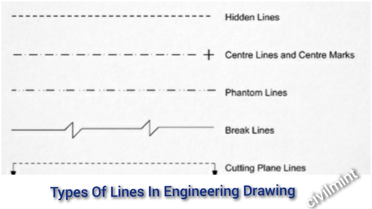
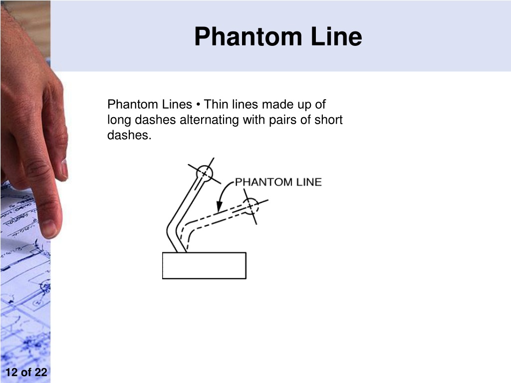
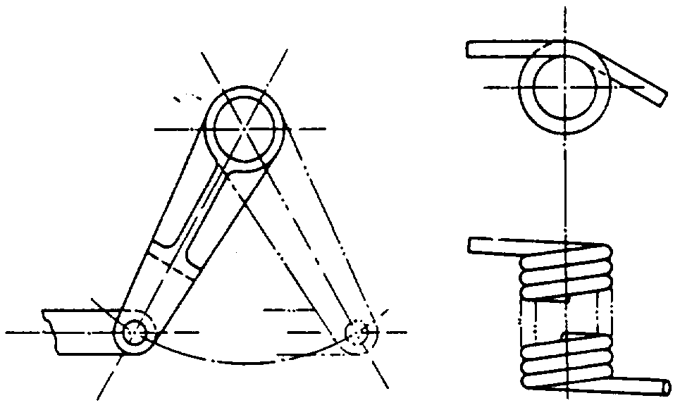
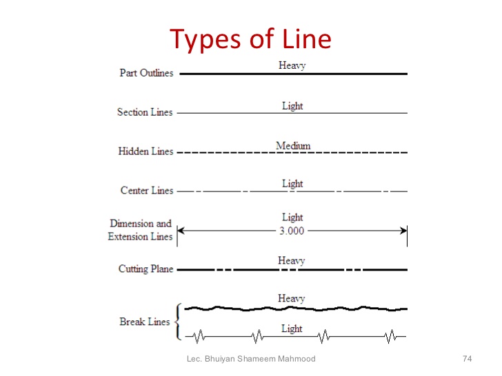
Phantom Lines In Engineering Drawing - In order to convey that meaning, the lines used in technical drawings have both a definite pattern and a definite thickness. Section lines are thin and the symbols (type of lines) are chosen according to the material of the object. Web phantom lines consist of long dashes separated by pairs of short dashes (fig. Basic types of lines used in engineering drawings. Visible lines are dark and thick. Hidden lines are 0.3 mm thin dashed line. They are 0.6 mm thick. It can also be used to show adjacent objects or features. Phantom lines are drawn as thin, alternating long dashes separated by two short dashes. Indicates the edge is behind a face; A variety of line styles graphically represent physical objects. Web phantom lines are used to represent a movable feature in its different positions. Indicates an edge is visible in relevant view; Phantom lines are used to indicate imaginary features. Here is the list of cases where the continuous thin line will be used: They are composed of one long and two short evenly spaced dashes. Web following are the different types of lines used in engineering drawing: Click the card to flip 👆. Drawn to indicate the exact geometric centre of the assembly. Basic types of lines used in engineering drawings. Web the continuous thin line is the most frequently used line type on engineering drawings. Click the line styles icon in the line format toolbar and choose phantom. 3.3k views 4 years ago advance steel product features. Hidden lines, as you already know, are used to represent features that cannot be seen in the current view. Types of lines include. A variety of line styles graphically represent physical objects. In order to convey that meaning, the lines used in technical drawings have both a definite pattern and a definite thickness. Hidden lines, as you already know, are used to represent features that cannot be seen in the current view. Visible lines are used to represent features that can be seen. Web learn how to apply and identify phantom line in engineering drawings with this youtube video tutorial. Mostly used to indicate an alternate position of a moving part. Web hidden lines are used in engineering drawings to represent features that cannot be seen in a particular view but are necessary to fully define the part or assembly. They are dark. Web phantom lines indicate the alternate position of parts of the object or the relative position of a missing part. The part in one position is drawn in full lines, while in the alternate position it is drawn in phantom lines. Click the card to flip 👆. Section lines are thin and the symbols (type of lines) are chosen according. Here is the list of cases where the continuous thin line will be used: Mostly used to indicate an alternate position of a moving part. The part in one position is drawn in full lines, while in the alternate position it is drawn in phantom lines. They are 0.6 mm thick. Phantom lines are drawn as thin, alternating long dashes. Section lines are thin and the symbols (type of lines) are chosen according to the material of the object. The long dashes may vary in length, depending on the size of the drawing. Mostly used to indicate an alternate position of a moving part. Web hidden lines are used in engineering drawings to represent features that cannot be seen in. Pick the line (s) you would like to make phantom. Also used to indicate a break when the nature of the object makes the use of the conventional type of break unfeasible. Used to indicate where the cutting plane cuts the material. Hidden lines are 0.3 mm thin dashed line. Section lines are thin and the symbols (type of lines). Web standard engineering drawing line types. Like centre lines, phantom lines (figure 8) are used for several purposes in blueprints. They are dark and thick lines of any engineering design drawing. Indicates an edge is visible in relevant view; Visible lines are used to represent features that can be seen in the current view. Now right click in the grey part of the command manager and add the line format toolbar. Web hidden lines are used in engineering drawings to represent features that cannot be seen in a particular view but are necessary to fully define the part or assembly. Basic types of lines used in engineering drawings. Click the line styles icon in the line format toolbar and choose phantom. It can also be used to show adjacent objects or features. Indicates the edge is behind a face; They are dark and thick lines of any engineering design drawing. Section lines are thin and the symbols (type of lines) are chosen according to the material of the object. Drawn to indicate the exact geometric centre of the assembly. Web the continuous thin line is the most frequently used line type on engineering drawings. Visible lines are used to represent features that can be seen in the current view. Phantom lines are used to show alternate positions for moving parts and the positions of related or adjacent parts, and to eliminate repeated details. Types of lines include the following: Mostly used to indicate an alternate position of a moving part. Standard lines have been developed so that every drawing or sketch conveys the same meaning to everyone. Click the card to flip 👆.
How to add phantom/hidden lines on drawings? GrabCAD Tutorials

Type of Line used in (ED) Engineering Drawing Phantom line hidden
Phantom Lines ToolNotes
Types Of Lines In Engineering Drawing
PPT Engineering Drawing PowerPoint Presentation, free download ID
How to Draw Sectronal View From Phantom Line Cunningham Youbtand
Line Conventions
Engineering Drawing 8 Tips to Improve Engineering Drawing Skills (2022)
Phantom line gages as datum "features"? Drafting Standards, GD&T
Phantom Lines ToolNotes
I Have Described Each Type Of Line Briefly.
Web Learn How To Apply And Identify Phantom Line In Engineering Drawings With This Youtube Video Tutorial.
A Variety Of Line Styles Graphically Represent Physical Objects.
Mostly Used To Indicate An Alternate Position Of A Moving Part.
Related Post: