P Id Drawings
P Id Drawings - P&ids are used to develop guidelines and standards for facility operation. Web drawings are engineering’s international language engineers all over the world can understand them. Through a p&id, you can get the following information: It is the basic training document to explain the process details to operation guys,. Web p&id drawings 201: Web a piping and instrumentation diagram (p&id) is a comprehensive schematic that illustrates the functional relationship of piping, instrumentation, and system equipment components within a process plant. The shapes in this legend are representative of the functional relationship between piping, instrumentation, and system equipment units. It is currently not possible to get exactly the same list for 3d models as there are several propertie,like from and to, not available for 3d model components. Piping & instrumentation diagram explained. This means if some system is shown on a single pfd, it may require multiple p&id sheets to show the same system on p&id. Web you will learn how to read p&id and pefs with the help of the actual plant drawing. Web a piping and instrumentation diagram (p&id) is a comprehensive schematic that illustrates the functional relationship of piping, instrumentation, and system equipment components within a process plant. Piping & instrumentation diagram explained. P&id is short for “piping and instrumentation diagram”. Types of. The shapes in this legend are representative of the functional relationship between piping, instrumentation, and system equipment units. It serves as a blueprint that outlines the interconnection of piping, equipment, instrumentation, and controls within a. Web the line list report itself in data manager or report creator is only available for p&id drawings but not for 3d models. If you. Web p&id is a graphical representation of the actual process plant using various symbols that represent actual equipment. Elements of a p&id • equipment & valves identified • instrumentation type & location identified Web what is a p&id drawing? As said earlier, it is more complex than pfd. Web a piping and instrumentation diagram (p&id or pid) is a detailed. As this diagram covers many types of diagrams as the variety in industries is vast, many symbols are required. P&ids are used to develop guidelines and standards for facility operation. Web p&id drawings 201: Create yours using lucidchart for free when you sign up! Web p&ids are a schematic illustration of the functional relationship of piping, instrumentation and system equipment. The following diagrams will have more detail than in the first post. These diagrams provide a map for the engineering system's design which is helpful to problem identification and solving. Web you will learn how to read p&id and pefs with the help of the actual plant drawing. Web visual paradigm's p&id tool features a handy diagram editor that allows. P&id is more complex than pfd and includes lots of details, because of th. Web all images are free to use! Web the p&id drawing is usually used in the process industry and engineering field. A single pfd can have multiple p&ids. P&id diagrams are made with specific and standard shapes and symbols. 357k views 3 years ago basic instrumentation. These diagrams provide a map for the engineering system's design which is helpful to problem identification and solving. P&id is short for “piping and instrumentation diagram”. Web p&ids are a schematic illustration of the functional relationship of piping, instrumentation and system equipment components used in the field of instrumentation and control or automation.. The following diagrams will have more detail than in the first post. It serves as a blueprint that outlines the interconnection of piping, equipment, instrumentation, and controls within a. Web p&id drawing is a schematic representation of instrumentations, control systems, and pipelines used in any process development plant. Through a p&id, you can get the following information: The mechanical and. Types of drawings •process flow diagrams: P&id symbols refer to the standard notations and graphical representations used on piping and instrumentation diagrams (p&ids) to depict the components and systems involved in process flows within a facility. Piping and instrumentation diagrams are useful instruments when it comes to the design, modification, and maintenance of an engineering process. P&id is more complex. Web you will learn how to read p&id and pefs with the help of the actual plant drawing. Web how to read p&id drawing easily. P&id is more complex than pfd and includes lots of details, because of th. Through a p&id, you can get the following information: Web drawings are engineering’s international language engineers all over the world can. P&id is more complex than pfd and includes lots of details, because of th. P&ids are used to develop guidelines and standards for facility operation. Elements of a p&id • equipment & valves identified • instrumentation type & location identified Web the line list report itself in data manager or report creator is only available for p&id drawings but not for 3d models. Web p&id drawing, or piping and instrumentation diagrams, is like a special map that shows how pipes and instruments work together in factories and plants. It serves as a blueprint that outlines the interconnection of piping, equipment, instrumentation, and controls within a. It is currently not possible to get exactly the same list for 3d models as there are several propertie,like from and to, not available for 3d model components. Web piping and instrumentation diagrams (p&ids) use specific symbols to show the connectivity of equipment, sensors, and valves in a control system. Reading real world examples | corso systems. Web a piping and instrumentation diagram (p&id or pid) is a detailed diagram in the process industry which shows the piping and process equipment together with the instrumentation and control devices. In report creator you can use the default template 3d parts 357k views 3 years ago basic instrumentation. It's a simple way of using lines and symbols to tell the story of how liquids and gases move around, and how machines control them. As said earlier, it is more complex than pfd. Web all images are free to use! Web piping and instrumentation diagrams, or p&ids, are used to create important documentation for process industry facilities.
P & ID Diagram. How To Read P&ID Drawing Easily. Piping

Learn How to Read P&ID Drawings A Complete Guide
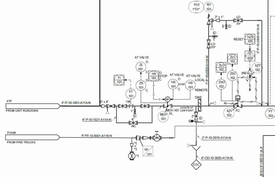
Learn How to Read P&ID Drawings A Complete Guide (2023)
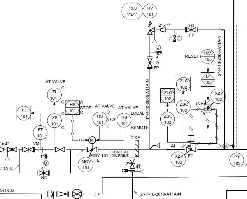
Learn How to Read P&ID Drawings A Complete Guide (2023)
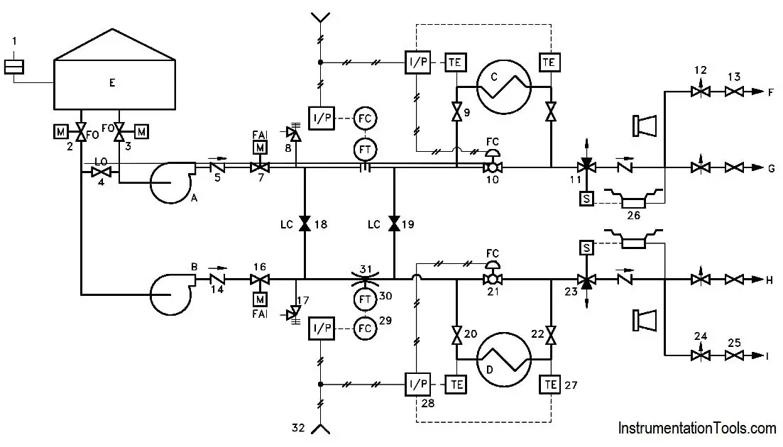
Piping and Instrumentation Documents Instrumentation Tools
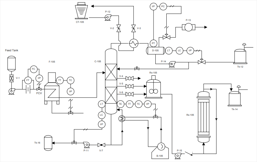
How to Read a P&ID Drawing Quickly and Easily Edraw Max
P&ID Examples Lucidchart
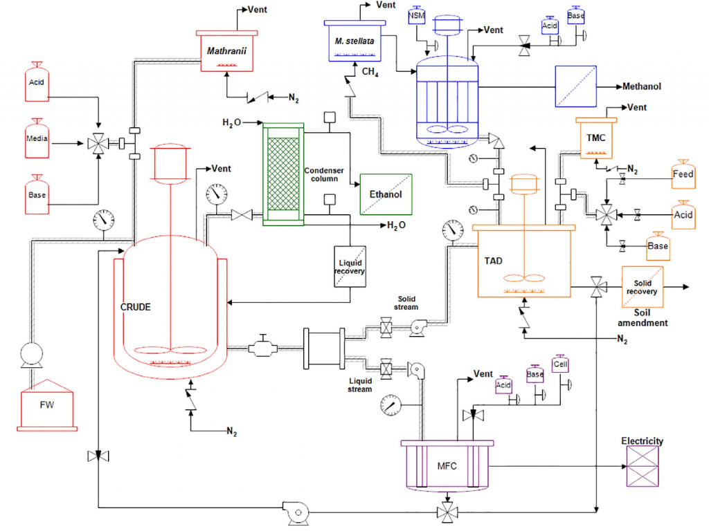
Piping & Instrumentation Diagrams (P&IDs) Punchlist Zero

How to Read and Interpret Piping and Instrumentation Diagrams (P&ID
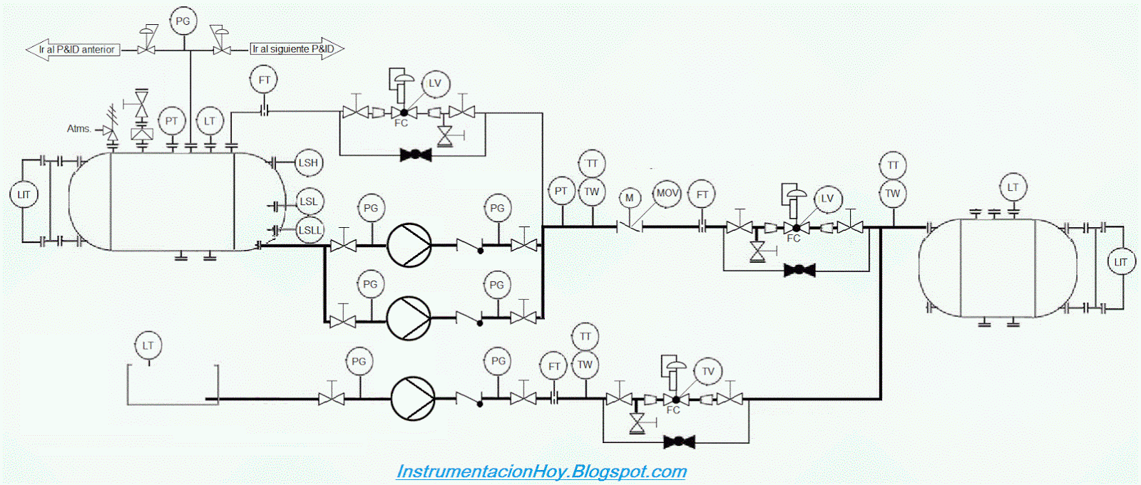
P&ID EXAMPLE
Web P&Id Is A Graphical Representation Of The Actual Process Plant Using Various Symbols That Represent Actual Equipment.
Web You Will Learn How To Read P&Id And Pefs With The Help Of The Actual Plant Drawing.
Web P&Id Drawing Is A Schematic Representation Of Instrumentations, Control Systems, And Pipelines Used In Any Process Development Plant.
P&Id, Short For Piping And Instrumentation Diagram, Is A Crucial Visual Representation In The Field Of Engineering.
Related Post:
