Legend In Engineering Drawing
Legend In Engineering Drawing - Web an engineering drawing is a type of technical drawing that is used to convey information about an object. Web if you want to learn how to read p&id and pfd, you must know the legend used in these drawings. The link is available in the description. This information is displayed in the areas surrounding the graphic portion of the drawing. Web following elements are required to comprehend for reading an engineering drawing. So please watch the video till the end. Web engineering symbology, prints, & drawings intro to print reading 2 anatomy of a drawing a generic engineering drawing can be divided into the following five major areas or parts. Interpretation of scales in civil engineering: Web a convenient guide for geometric dimensioning and tolerancing (gd&t) symbols at your fingertips. You can download this presentation for free. These elements and codes act as alphabets of the engineering drawing. Web the notes and legends section of a drawing lists and explains any special symbols and conventions used on the drawing, as illustrated below. Web a key or legend is provided to help make the drawing as clear and easy to understand as possible. It could be a mechanical,. Web if you want to learn how to read p&id and pfd, you must know the legend used in these drawings. Extraction of the table of legends from the design or drawing. A common use is to specify the geometry necessary for the construction of a component and is called a detail drawing. The first four parts listed above provide. Web block, the notesand legend, and the drawing grid is necessarybefore a drawing can be read. As an engineering drawing displays the exact picture of an object, it obviously conveys the same ideas to every trained eye. Web a legend simply put is a chart with all of the symbols used in an individual diagram. Chapter 1 provided a detailed. Eo 1.2 state how the grid system on an engineering drawing is. There are columns for the trace graphic, trace description, total quantity for all measurements using the trace and unit of measure. Web the drawing legend displays a grid of all traces used in a drawing. Click on the links below to learn more about each gd&t symbol or. Eo 1.1 state the five types of information provided in the title block of an engineering drawing. Chapter 1 provided a detailed summary of the major approaches to their segmentation, and here we describe our own contributions on some specific applications. The link is available in the description. As an engineering drawing displays the exact picture of an object, it. Web identify the 5 key sections of your piping isometrics (title block, grid system, revision block, notes and legend, engineering drawing block) know and identify valve symbols on your piping isometrics (gate, globe, ball, butterfly, needle…) Pfd is a process flow diagram. Web engineering drawing is a suitable graphic language from which any trained person can visualise the required object.. Web if you want to learn how to read p&id and pfd, you must know the legend used in these drawings. Web maximum engineering students have a question that what is a legend in engineering drawing, so here we are discussing about the legend. Eo 1.2 state how the grid system on an engineering drawing is. Web you can find. Web the major components of the proposed work are: Web engineering drawing is a suitable graphic language from which any trained person can visualise the required object. Web a legend simply put is a chart with all of the symbols used in an individual diagram. If you want to make yo. Web a convenient guide for geometric dimensioning and tolerancing. Also listed in the notes section is any information the designer or draftsman felt was necessary to. If you want to make yo. Pfd is a process flow diagram. Web a legend simply put is a chart with all of the symbols used in an individual diagram. Web engineering drawing is a suitable graphic language from which any trained person. Engineering drawing (graphic portion) the information contained in the drawing itself will be covered in subsequent modules. Pfd and p&id are also known as pfs and pefs. Web if you want to learn how to read p&id and pfd, you must know the legend used in these drawings. English [auto], korean [auto], 1 more. Web the drawing legend displays a. Pfd and p&id are also known as pfs and pefs. Obtaining the template symbols and their corresponding names/class information. This information is displayed in the areas surrounding the graphic portion of the drawing. Also listed in the notes section is any information the designer or draftsman felt was necessary to. Chapter 1 provided a detailed summary of the major approaches to their segmentation, and here we describe our own contributions on some specific applications. Know read understand piping & instrumentation diagrams p&ids. Extraction of the table of legends from the design or drawing. A key can be used in a number of ways. Web a key or legend is provided to help make the drawing as clear and easy to understand as possible. Web identify the 5 key sections of your piping isometrics (title block, grid system, revision block, notes and legend, engineering drawing block) know and identify valve symbols on your piping isometrics (gate, globe, ball, butterfly, needle…) know the standards and conventions for valve status (open, closed, throttled) The meaning of an engineering drawing is expressed through text and graphics and the relations between them. Web the major components of the proposed work are: Web maximum engineering students have a question that what is a legend in engineering drawing, so here we are discussing about the legend. Web you can find that whenever such drawings have legend charts in them, a user can easily distinguish the difference between drawings. Web an engineering drawing is a type of technical drawing that is used to convey information about an object. Engineering drawing notes and legend.
Mechanical Engineering Drawing Symbols Pdf Free Download at

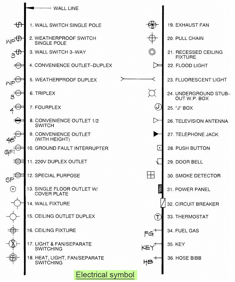
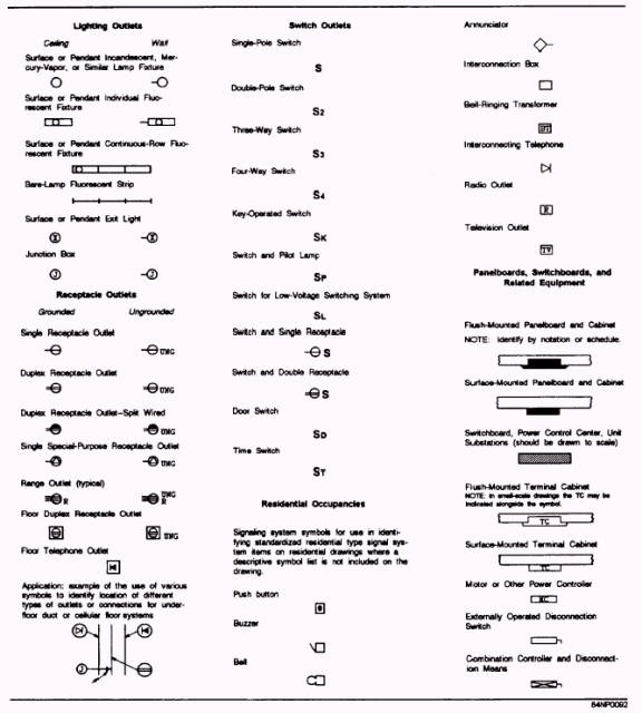
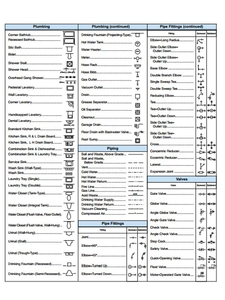
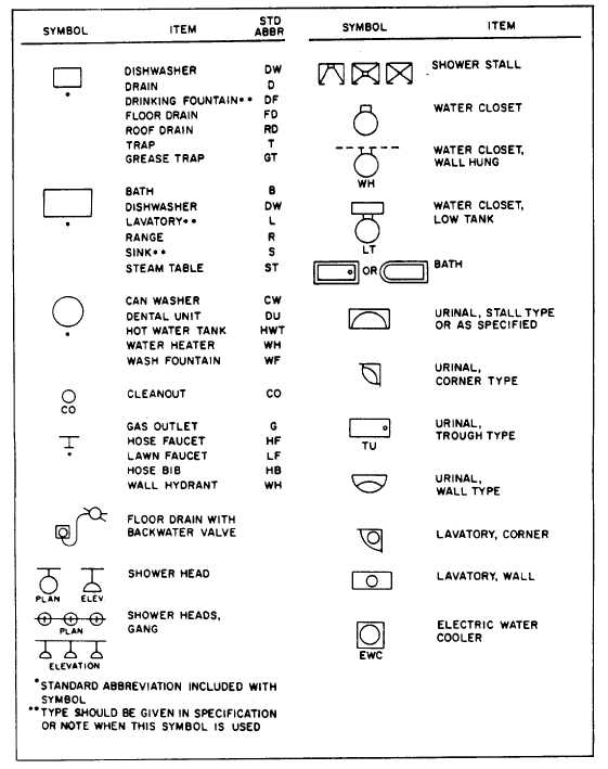
R.Land Baidin Egwar, ST MECHANICAL AND ELECTRICAL LEGEND AND SYMBOLS

Civil Engineering Drawing Symbols And Their Meanings at PaintingValley

Engineering Drawing Symbols And Their Meanings Pdf at PaintingValley

Mechanical Drawing Symbols Technical Drawing Software Mechanical
Engineering Drawing Symbols And Their Meanings Pdf at PaintingValley
Engineering Drawing Symbols And Their Meanings Pdf at PaintingValley

Figure 24.Sample legend of symbols.
Civil Engineering Drawing Symbols And Their Meanings at PaintingValley
Civil Engineering Drawing Symbols And Their Meanings at PaintingValley
Graphical Symbols And Notations Should Be Defined Where They Are First Used, Or On The General Note Sheet, And Other Sheets Can Thereafter Use A Note To Refer To The Legend.
This Is An Invaluable Tool Because It Simply Is Not Possible To Remember Every Single Symbol Used In.
A Legend On Construction Drawings Acts As A Comprehensive Dictionary, Detailing What Each Symbol, Abbreviation Or Acronym Featured In The Drawing Set Means.
Click On The Links Below To Learn More About Each Gd&T Symbol Or Concept, And Be Sure To Download The Free Wall Chart For A Quick Reference When At Your Desk Or On The Shop Floor.
Related Post: