How To Draw Bode Diagram
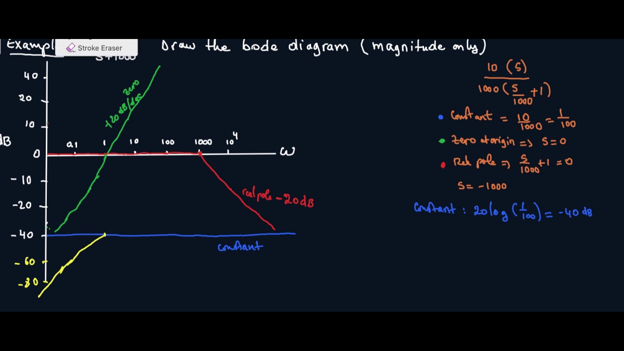
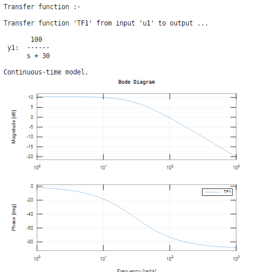
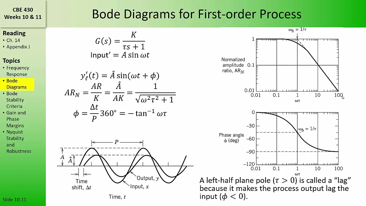
How To Draw Bode Diagram - Web dear tutor please help me out in this question, your efforts will be appreciated a system is represented by a transfer function as follows: Bode plots are a very useful way to represent the gain and phase of a system as a function of frequency. Draw the bode diagram for each part. Builds on the previous video by showing how some asymptotic information in the bode plot can be obtained with minimal. The plot displays the magnitude (in db) and phase (in. Bode(sys) creates a bode plot of the frequency response of a dynamic system model sys. Connect with straight line from ω = ω0. See examples, definitions, and techniques for different types of. A bode plot consists of two separate plots, one for. Web the bode diagram of an electronic circuit consists of two graphs that plot respectively the gain gdb and the phase difference as a function of the frequency in logarithmic scale. 81k views 8 years ago. Web bode plots give engineers a way to visualize the effect of their circuit, in terms of voltage magnitude and phase angle (shift). Web making a bode diagram. Web ωω = ∠hh jj ωω = ∠䍒ꎗnn䍒ꎖ jj ωω− ∠ष볡ष볢䍒ꎗ jj ωω = ∠aa jj ωω−∠擨月 jj ωω +∠ᘀjj ωω−∠ष볡. To interactively shape the open. A bode plot consists of two separate plots, one for. Web dear tutor please help me out in this question, your efforts will be appreciated a system is represented by a transfer function as follows: Next, identify the factors like k, poles and zeros at the. Web learn how to draw bode diagrams for transfer functions using logarithmic plots of. Firstly, write the given transfer function in the time constant form. The plot displays the magnitude (in db) and phase (in. To interactively shape the open. Web bode plots give engineers a way to visualize the effect of their circuit, in terms of voltage magnitude and phase angle (shift). 81k views 8 years ago. Web ωω = ∠hh jj ωω = ∠䍒ꎗnn䍒ꎖ jj ωω− ∠ष볡ष볢䍒ꎗ jj ωω = ∠aa jj ωω−∠擨月 jj ωω +∠ᘀjj ωω−∠ष볡. Builds on the previous video by showing how some asymptotic information in the bode plot can be obtained with minimal. Draw your vertical and horizontal axis. Web bode plots give engineers a way to visualize the effect of their. See examples, definitions, and techniques for different types of. Bode diagrams this handout is a complement to the textbook, own chapter 9 (section 9.4 in particular); Builds on the previous video by showing how some asymptotic information in the bode plot can be obtained with minimal. 81k views 8 years ago. G (s) = 10( s + 3 ) /. Web the bode diagram of an electronic circuit consists of two graphs that plot respectively the gain gdb and the phase difference as a function of the frequency in logarithmic scale. To interactively shape the open. Web making a bode diagram. Firstly, write the given transfer function in the time constant form. Following the discussion above, the way to make. −40 −20 0 20 40 magnitude (db) 103 104 105 106 107 ω (rad/s). G (s) = 10( s + 3 ) / s(s + 2)(s2 + s + 2) a. 81k views 8 years ago. Web making a bode diagram. See examples, definitions, and techniques for different types of. The plot displays the magnitude (in db) and phase (in. Bode(sys) creates a bode plot of the frequency response of a dynamic system model sys. Draw your vertical and horizontal axis. Connect with straight line from ω = ω0. G (s) = 10( s + 3 ) / s(s + 2)(s2 + s + 2) a. Web bode plots give engineers a way to visualize the effect of their circuit, in terms of voltage magnitude and phase angle (shift). Web ωω = ∠hh jj ωω = ∠䍒ꎗnn䍒ꎖ jj ωω− ∠ष볡ष볢䍒ꎗ jj ωω = ∠aa jj ωω−∠擨月 jj ωω +∠ᘀjj ωω−∠ष볡. Bode(sys) creates a bode plot of the frequency response of a dynamic system model sys. Following. Firstly, write the given transfer function in the time constant form. Builds on the previous video by showing how some asymptotic information in the bode plot can be obtained with minimal. Bode plots are a very useful way to represent the gain and phase of a system as a function of frequency. Draw the bode diagram for each part. Connect. Web the bode diagram of an electronic circuit consists of two graphs that plot respectively the gain gdb and the phase difference as a function of the frequency in logarithmic scale. Web the steps to sketch the bode plot are as follows: Draw your vertical and horizontal axis. | drawing bode plots has never been so easy. Web making a bode diagram. 15k views 10 years ago bode diagrams. Detailed instructions on how to draw a bode plot diagram on first order denominators and integrators. Web ωω = ∠hh jj ωω = ∠䍒ꎗnn䍒ꎖ jj ωω− ∠ष볡ष볢䍒ꎗ jj ωω = ∠aa jj ωω−∠擨月 jj ωω +∠ᘀjj ωω−∠ष볡. Web draw the bode plot from a transfer function using the bode plot generator. Firstly, write the given transfer function in the time constant form. A bode plot is a graphical representation that shows how the gain (magnitude) and phase of a system respond. Identify individual terms and convert transfer function to standard form. A time delay of 0.01 seconds (magnitude and phase of time delay described here ). G (s) = 10( s + 3 ) / s(s + 2)(s2 + s + 2) a. See examples, definitions, and techniques for different types of. Bode(sys) creates a bode plot of the frequency response of a dynamic system model sys.
Bode Plot Example Bode Diagram Example MATLAB Electrical Academia

Bode Plot Example Bode Diagram Example MATLAB Electrical Academia

ME 340 Example Drawing Bode Plot of a Transfer Function 2 YouTube
How to Draw a Bode Plot (Part 2) YouTube
[Solved] How to draw the bode diagram for this function with all work
How To Draw Bode Diagram Hellknife18

simple method to draw bode plot3 YouTube

How to draw bode diagram for electrochemical system YouTube
CBE 430 Week 10 04 Bode diagrams part 1 YouTube

Bode Plot EXAMPLE YouTube
Connect With Straight Line From Ω = Ω0.
Bode Plots Are A Very Useful Way To Represent The Gain And Phase Of A System As A Function Of Frequency.
Web Bode Plots Give Engineers A Way To Visualize The Effect Of Their Circuit, In Terms Of Voltage Magnitude And Phase Angle (Shift).
A Bode Plot Consists Of Two Separate Plots, One For.
Related Post: