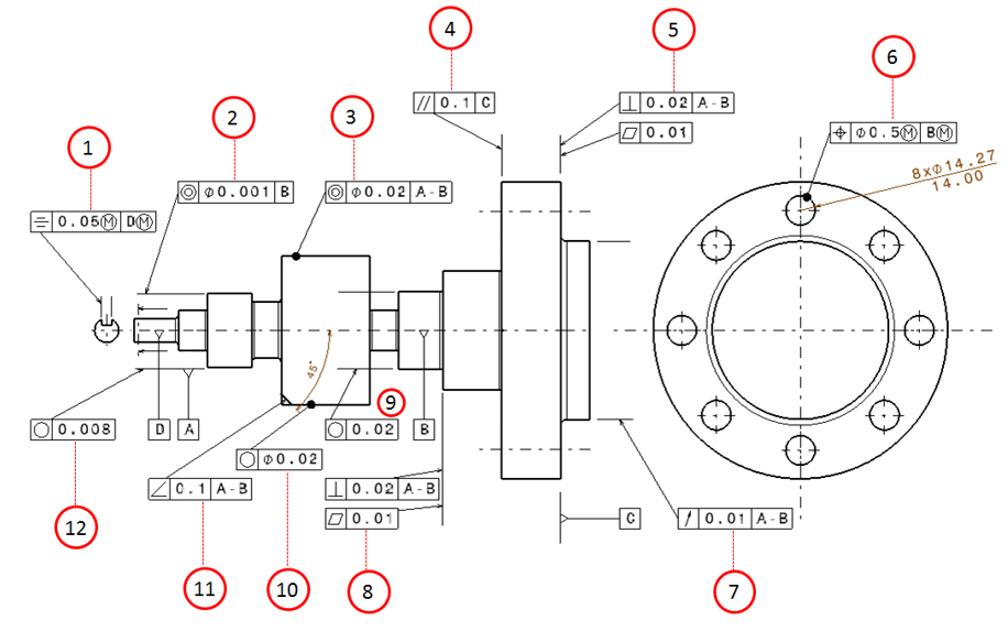
Gd And T Drawings
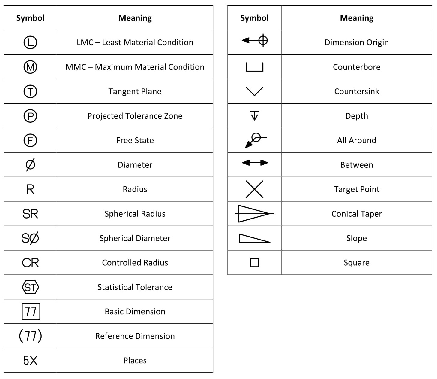
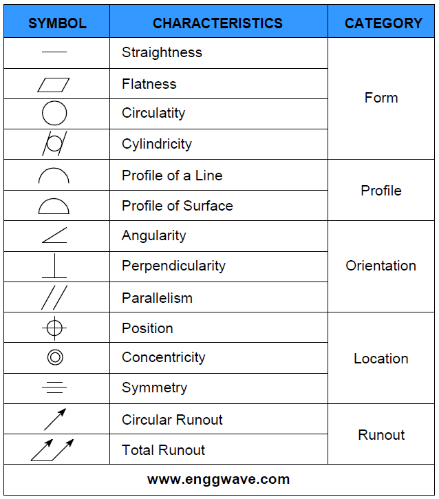
Gd And T Drawings - Currently, we have 16 symbols for geometric tolerances, which are categorized according to the tolerance they specify. Tolerance zone shape and dimensions. Used to specify the most protruded part and the most concaved part. Part features are critical to function or interchangeability. Used to specify how close a target should be to a perfect circle. Web a convenient guide for geometric dimensioning and tolerancing (gd&t) symbols at your fingertips. Web what is gd & t ? Gd&t aims to communicate the design intent in a way that the desired form, fit, function, and interchangeability of feature is conveyed on the drawings without confusion. It is important though that datum features are indicated correctly on the drawing to ensure that the. It is a common symbol that references how flat a surface is regardless of any other datums or features. Web what is gd & t ? Web gd&t drawings and symbols. Tolerancing systems (asme y14.5, etc.) datums, form, orientation, location, and size. Review the slides use your reference material to find the errors. When to use gd & t ? Currently, we have 16 symbols for geometric tolerances, which are categorised according to the tolerance they specify. Used to specify the most protruded part and the most concaved part. Used to specify how close a target should be to a perfect circle. It is a common symbol that references how flat a surface is regardless of any other datums or. As stated before, datums can be points, axes, lines, and planes or a combination thereof. Geometric dimensioning and tolerancing, by d. Engineering drawing and design by d. Web make better technical decisions. Web the asme y14.5 is an authoritative guideline and is a design language of geometric dimensioning and tolerancing (gd&t). Gd&t symbol or control symbol. Used to specify the most protruded part and the most concaved part. Tolerance zone shape and dimensions. Parts manufactured in a shop must meet specific design requirements shown on engineering drawings. Significant improvement over traditional tolerancing. Using gd&t results in a more accurate design, larger tolerances for less important design features, and cost savings for manufacturing. Click on the links below to learn more about each gd&t symbol or concept, and be sure to download the free wall chart for a quick reference when at your desk or on the shop floor. A feature control frame. Significant improvement over traditional tolerancing. Gd&t flatness is very straight forward. True position theory (size value in rectangular frame) Geometric tolerances are specified using symbols on a drawing. Gd&t symbol or control symbol. Web geometric dimensioning and tolerancing is a set of rules and gd&t symbols used on a drawing to communicate the intent of a design, focusing on the function of the part. Significant improvement over traditional tolerancing. When to use gd & t ? International standard to specify form, fit and function of parts. Web gd&t drawings and symbols. Used to specify how straight a target is. It is a common symbol that references how flat a surface is regardless of any other datums or features. International standard to specify form, fit and function of parts. Web gd&t is a particular set of conventions used on engineering drawings (often called “prints” from the older “blueprints”) that communicate how parts. Web notation is important on drawings. This course will teach you the basics of how to understand gd&t symbols and their use. Watch the top 3 mistakes in engineering drawings to learn firsthand how to avoid these critical mistakes. Ansi y 14.5, iso 1101. By providing uniformity in drawing specifications and interpretation, geometric dimensioning and tolerancing reduces controversy, guesswork, and. Introduction to imprecision in manufacturing. International standard to specify form, fit and function of parts. Using gd&t results in a more accurate design, larger tolerances for less important design features, and cost savings for manufacturing. Currently, we have 16 symbols for geometric tolerances, which are categorized according to the tolerance they specify. Web what is gd & t ? Used to specify the most protruded part and the most concaved part. Geometric tolerances are specified using symbols on a drawing. Tolerance zone shape and dimensions. The feature control frame consists of four main pieces of information: Web gd&t is a particular set of conventions used on engineering drawings (often called “prints” from the older “blueprints”) that communicate how parts should fit together and how they function. Gd&t flatness is very straight forward. Gd&t is a way of specifying engineering design and drawing requirements with particular attention to actual function and relationship of. Review the slides use your reference material to find the errors. Web geometric dimensioning and tolerancing (gd&t or gd and t) is a language of symbols and standards designed and used by engineers and manufacturers to describe the shape (geometry) and size (dimensions) of a product and facilitate communication between entities working together to manufacture products. International standard to specify form, fit and function of parts. Classification and symbols of geometric tolerance characteristics. Engineering drawing and design by d. Web 5 steps to implement gd&t in your drawings. Parts manufactured in a shop must meet specific design requirements shown on engineering drawings. A feature control frame is used in geometric dimensioning and tolerancing to describe the conditions and tolerances of a geometric control on a part’s feature. Using gd&t results in a more accurate design, larger tolerances for less important design features, and cost savings for manufacturing.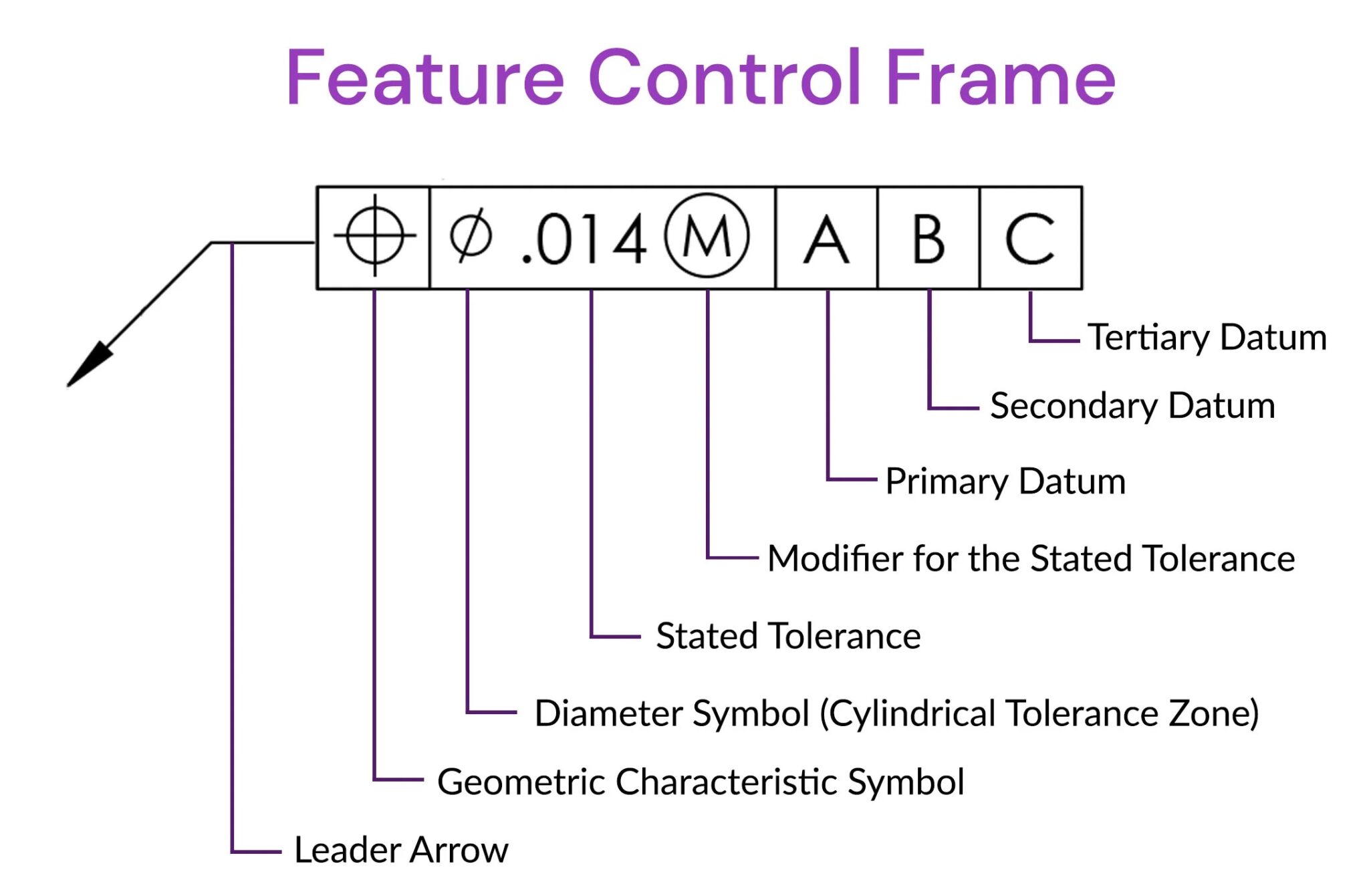
What are Geometric dimensioning and tolerancing GD & T Symbols
Design Tech Academy (1)Geometric Dimensioning and Tolerancing (GD&T

GD&T The Beginner's Guide to Geometric Dimensioning and Tolerancing
GD&T Drawings KOHLEX
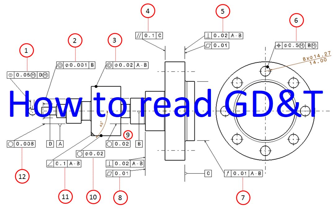
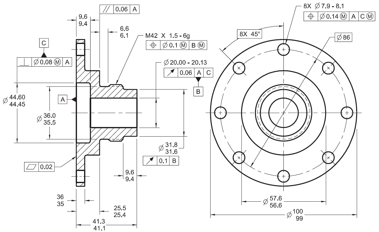
Examples on how to interpret GD&T Form, orientation, location and run
Examples on how to interpret GD&T Form, orientation, location and run

GD&T for beginners step by step approach to do gd&t for mechanical

Engineering Drawings & GD&T For the Quality Engineer Mechanical

GD&T 101 An Introduction to Geometric Dimensioning and Tolerancing
GD&T Symbols GD&T Terms Geometric Dimensioning and Tolerancing
True Position Theory (Size Value In Rectangular Frame)
Web What Is Gd & T ?
Classification And Symbols Of Geometric Tolerance Characteristics;
Gd&T Aims To Communicate The Design Intent In A Way That The Desired Form, Fit, Function, And Interchangeability Of Feature Is Conveyed On The Drawings Without Confusion.
Related Post: