Fillet Symbol In Engineering Drawing
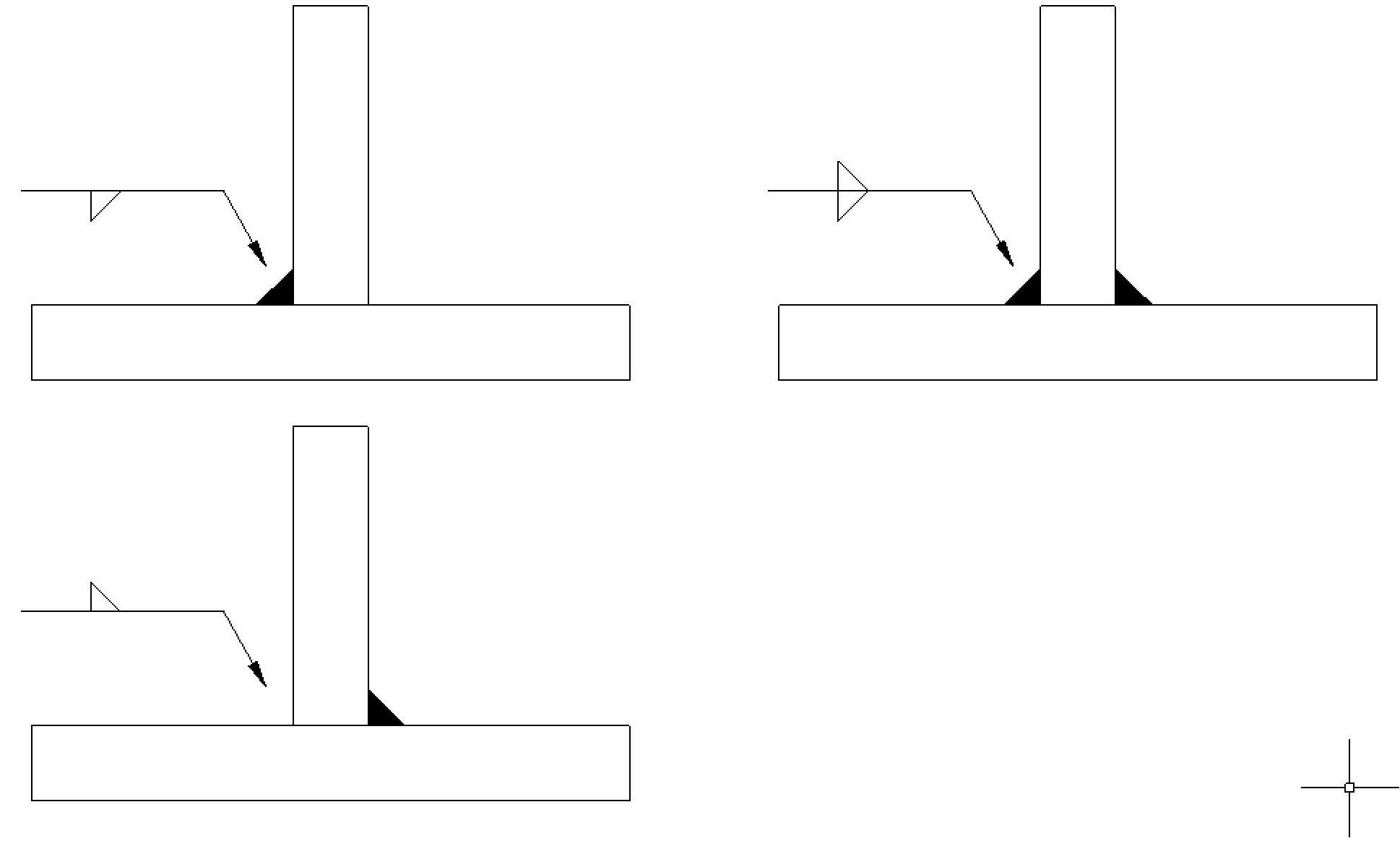
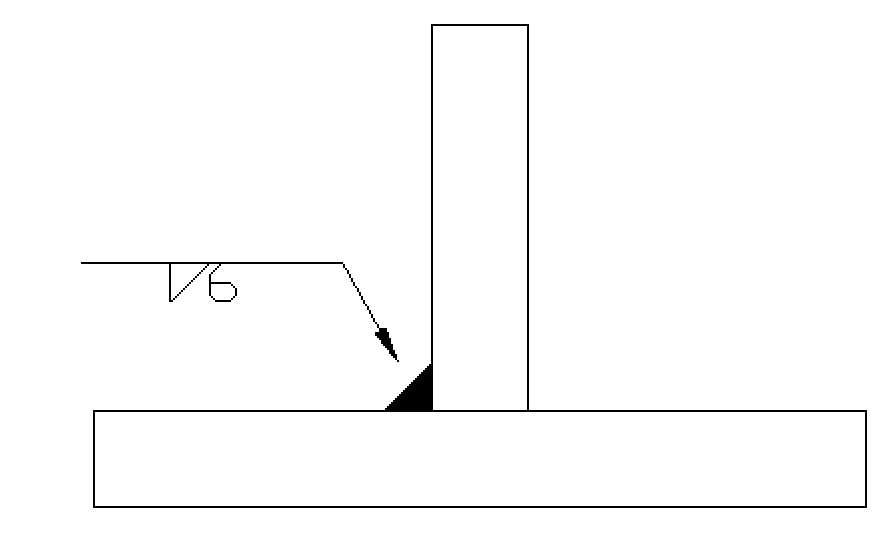
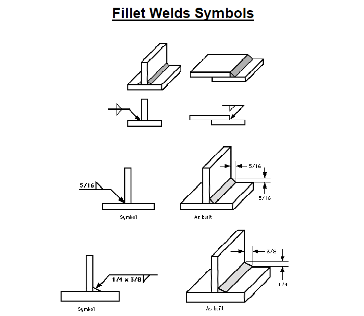
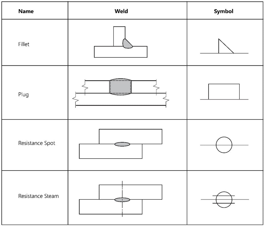
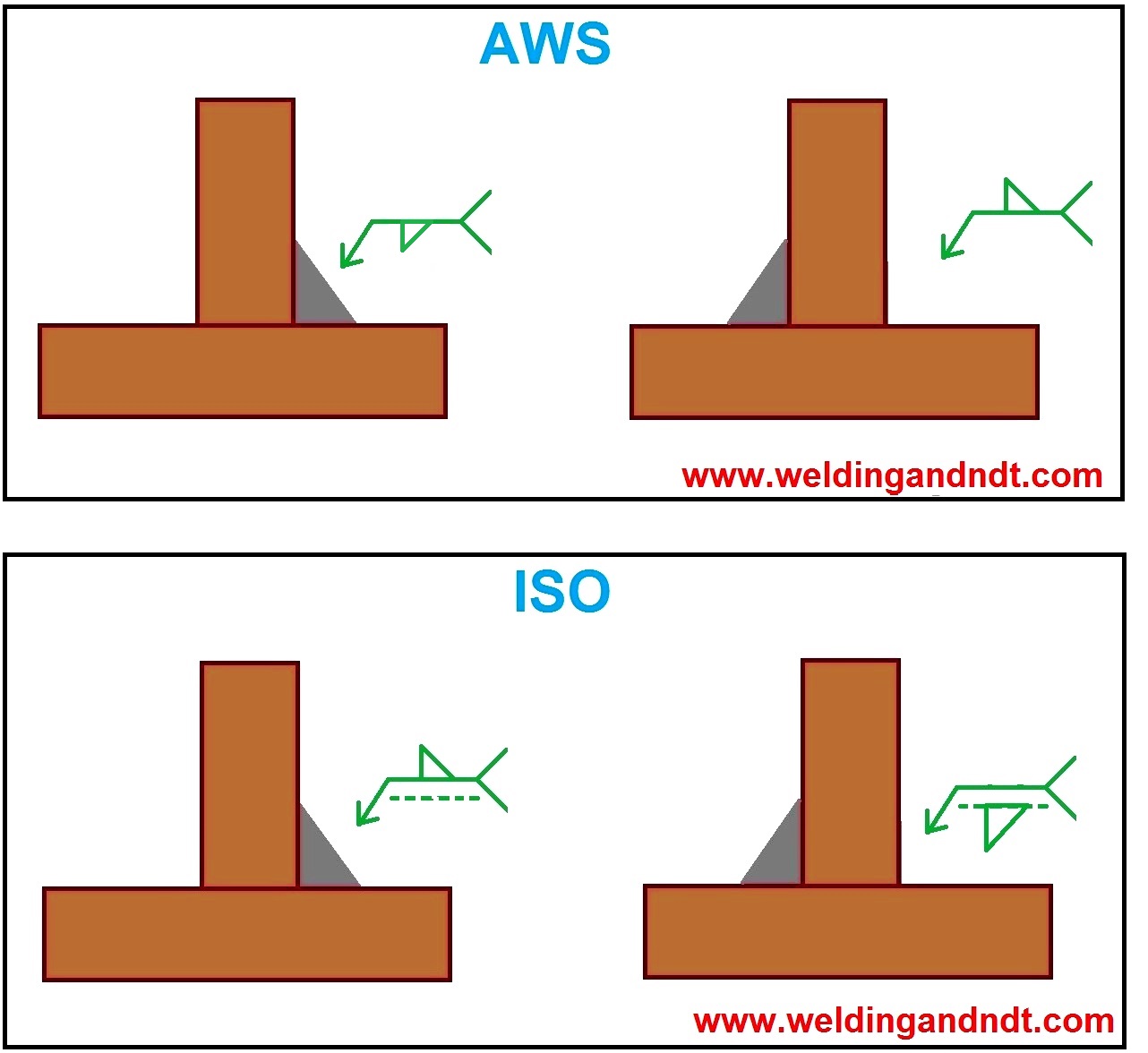
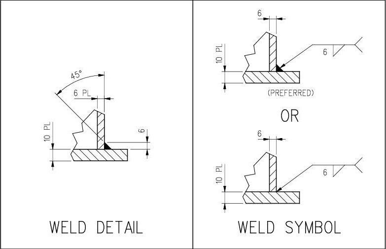
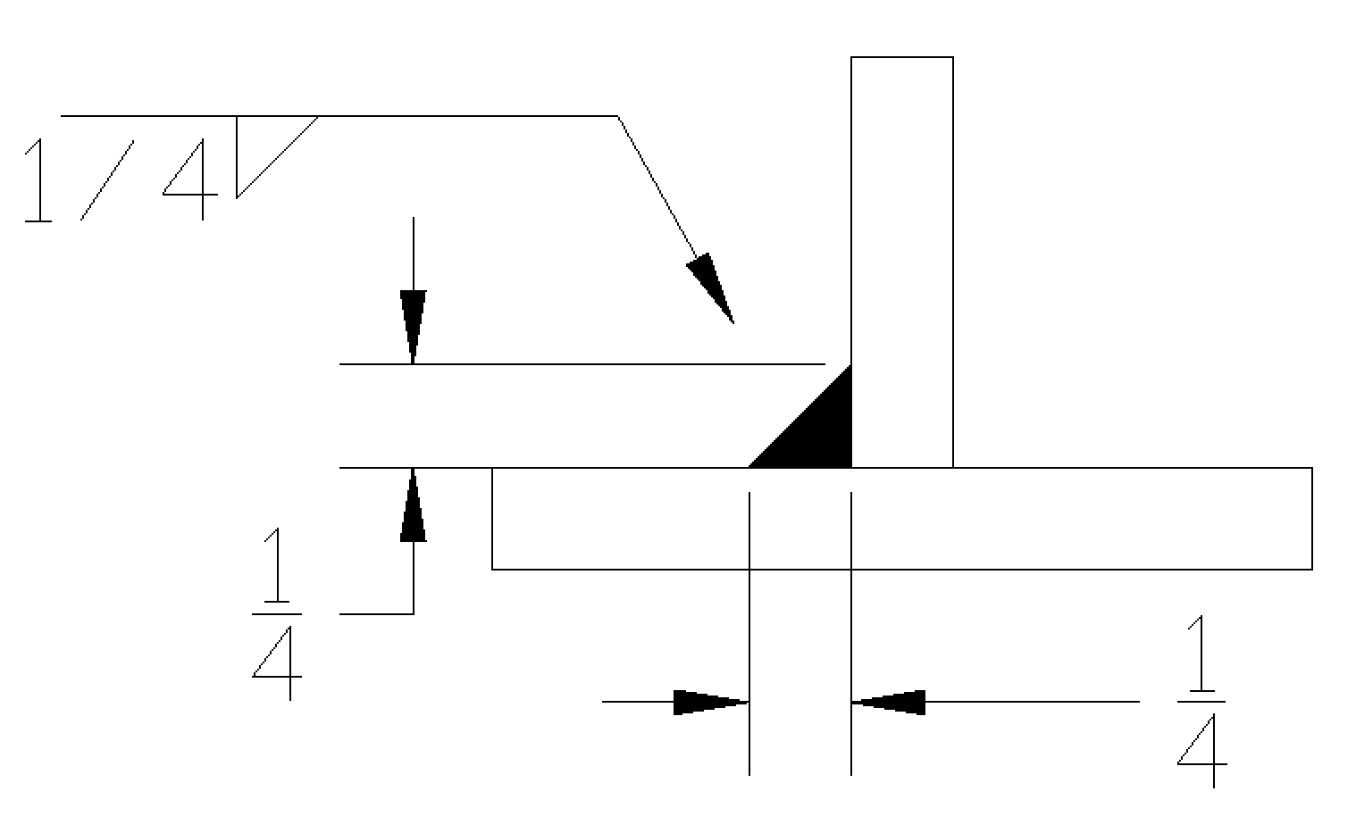
Fillet Symbol In Engineering Drawing - This list includes abbreviations common to the vocabulary of people who work with engineering drawings in the manufacture and inspection of parts and assemblies. Figure 8 gives examples of symbols used in different standards. When identification of the weld process is required as part of the weld symbol the relevant weld process code is listed in bs en iso 4063. Different types of basic weld symbols make up the fabrication or engineering drawings. These are called primary weld symbols. 1” stud welds on the arrow side, 2” pitch, 20 total studs. The following weld symbols are supported in iso: The standardization of these symbols by the iso upholds uniformity and clarity within the industry, ensuring that the symbols. Generally, but not in all cases, fillet welds are of equal legs. Web for fillet welds, numbers to the left of the symbol indicate the design throat thickness, leg length (leg size), or both design throat thickness and leg length requirements. The purpose of this page is to introduce you to the common symbols and their meaning. Radius of an arc or circle. The british standard for weld symbols was bs en 22553 which has been superseded by bs en iso 2553:2019. Web what are the most commonly used engineering drawing symbols and their meanings? These welds can be applied on. For example, a 0.5 inch fillet radius would be represented as: Web when welds are specified on engineering and fabrication drawings, a cryptic set of symbols issued as a sort of shorthand for describing the type of weld, its size, and other processing and finishing information. Web the weld_symbol_standard configuration option in the detail module enables you to set the. The standardization of these symbols by the iso upholds uniformity and clarity within the industry, ensuring that the symbols. Web the fillet weld symbol is a right triangle placed on the reference line with the perpendicular leg always on the left. Web a fillet weld symbol can be used with an arrow side (below reference line) other side (above reference. Web a weld symbol represents a particular type of weld (groove welding, fillet welding, plug welding, etc.) and always forms a part of the welding symbol drawn on a fabrication drawing. Web a fillet weld symbol can be used with an arrow side (below reference line) other side (above reference line) significance or on both sides (both sides of the. A fillet weld symbol can be used with an arrow side. Aws welding symbol chart (desk size) aws welding symbol chart (wall size) The aws defines a fillet weld as: 4.5 resistance seam weld symbols. Web the fillet weld symbol is a right triangle placed on the reference line with the perpendicular leg always on the left. Web engineering drawing abbreviations and symbols are used to communicate and detail the characteristics of an engineering drawing. The following weld symbols are supported in iso: This list includes abbreviations common to the vocabulary of people who work with engineering drawings in the manufacture and inspection of parts and assemblies. Each type of weld has its symbol. A fillet weld. Web welding symbols and drawings are essential for learning and understanding the correct way of welding. Web what are the most commonly used engineering drawing symbols and their meanings? Fillets and rounds are specified using the “radius” symbol, “r”. Web a fillet weld symbol can be used with an arrow side (below reference line) other side (above reference line) significance. These are called primary weld symbols. The aws defines a fillet weld as: When identification of the weld process is required as part of the weld symbol the relevant weld process code is listed in bs en iso 4063. The purpose of this page is to introduce you to the common symbols and their meaning. In the case of fillet. 3/16” spot weld on the arrow side, ground flush, a pitch of 2”, and 8 total welds. Web fillet weld symbols explained. Web when welds are specified on engineering and fabrication drawings, a cryptic set of symbols issued as a sort of shorthand for describing the type of weld, its size, and other processing and finishing information. Web the most. Web a weld symbol represents a particular type of weld (groove welding, fillet welding, plug welding, etc.) and always forms a part of the welding symbol drawn on a fabrication drawing. In the space below draw a symbol for the following: The purpose of this page is to introduce you to the common symbols and their meaning. Fillet welds are. The purpose of this page is to introduce you to the common symbols and their meaning. Web the weld_symbol_standard configuration option in the detail module enables you to set the symbol support for your drawings. A fillet weld symbol can be used with an arrow side. Flats and reversals (falling within the dimensional tolerance zone) are tolerated unless cr (controlled radius) is explicitly specified. Web construction drawing symbols ensure that construction documents are clear, concise and universally interpretable, facilitating global collaboration and contributing to the efficiency and success of construction projects. Web a fillet weld symbol can be used with an arrow side (below reference line) other side (above reference line) significance or on both sides (both sides of the reference line.) when a fillet weld is required on both sides of the reference line it. Fillets and rounds are specified using the “radius” symbol, “r”. In the case of fillet welding, the drawings and symbols and their correct interpretations are critical to learning the basics of fillet welding. Generally, but not in all cases, fillet welds are of equal legs. Web when welds are specified on engineering and fabrication drawings, a cryptic set of symbols issued as a sort of shorthand for describing the type of weld, its size, and other processing and finishing information. It involves depositing a weld along the edge of the metal, creating a triangular fillet shape. Web drawing of weld symbols. 4.3 plug weld and slot welding symbols. Each type of weld has its symbol. The aws defines a fillet weld as: Web the fillet weld symbol is a right triangle placed on the reference line with the perpendicular leg always on the left.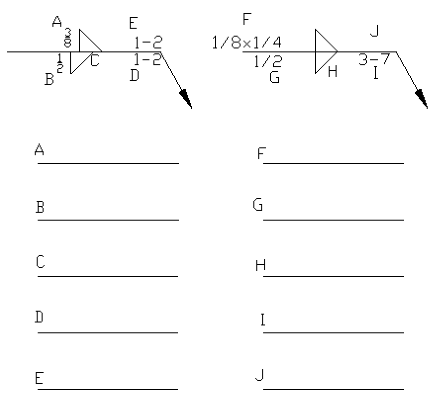
Fillet Weld Symbols On Drawings
![[SOLVED] In engineering drawing, the welding symbol used for fillet](https://storage.googleapis.com/tb-img/production/20/08/weld symbol1.PNG)
[SOLVED] In engineering drawing, the welding symbol used for fillet
1.6 Fillet Weld Symbols Workforce LibreTexts
Fillet Weld Symbols On Drawings
Understanding the Welding Symbols in Engineering Drawings Safe Work
Welding Symbols Chart An Explanation of the Basics (with Pictures
AutoCAD Fillet Command Applying Fillets to 2D and 3D Objects CAD CAM
Fillet Weld Symbol Chart
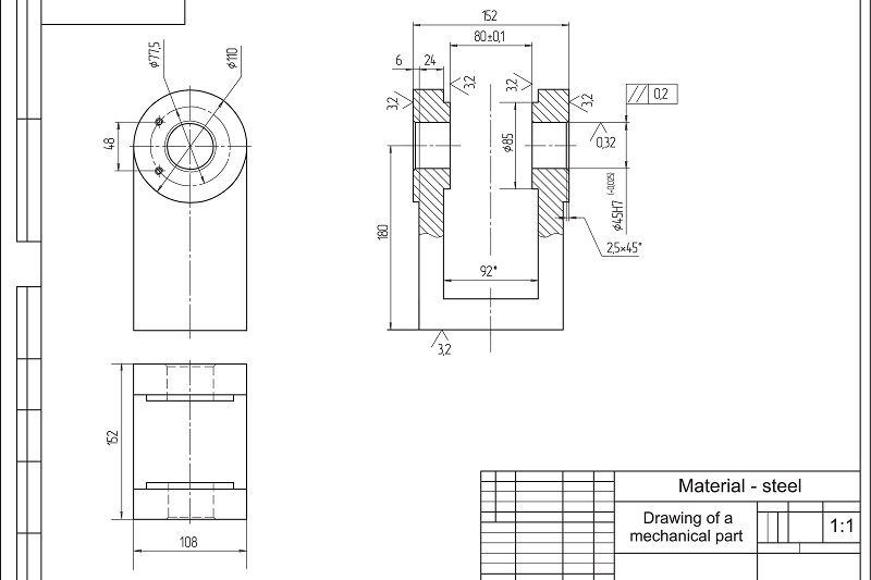
Dimensioning of welds Engineering Drawing Basics
Fillet Weld Symbols Interpretation of Metal Fab Drawings
1/4” Stud Welds On The Arrow Side With A.
Web A Weld Symbol Represents A Particular Type Of Weld (Groove Welding, Fillet Welding, Plug Welding, Etc.) And Always Forms A Part Of The Welding Symbol Drawn On A Fabrication Drawing.
Resistance Seam Weld With No Side Significance, 8” Pitch, 16” Length.
Web What Are The Most Commonly Used Engineering Drawing Symbols And Their Meanings?
Related Post: