Engineering Drawings Symbols
Engineering Drawings Symbols - Web it establishes symbols, rules, definitions, requirements, defaults, and recommended practices for stating and interpreting gd&t and related requirements for use on engineering drawings, models defined in digital data files, and in related documents. You can also check out the gd&t symbols and terms on our site. Web gd&t (geometric dimensioning and tolerancing) is a symbolic language used in engineering drawings to communicate design and manufacturing requirements. Here are more commonly used engineering drawing symbols and design elements as below. Learn the ins and outs of engineering drawing standards, such as iso and ansi, which govern the symbols, abbreviations, and notations. Currently, we have 16 symbols for geometric tolerances, which are categorized according to the tolerance they specify. Web engineering citation styles. It is more than simply a drawing, it is a graphical language that communicates ideas and information. The table shows dimensioning symbols found on drawings. Information appears in the following general order: The table shows dimensioning symbols found on drawings. Engineering graphics is used in the design process for visualization, communication, and documentation. Web engineering drawings (aka blueprints, prints, drawings, mechanical drawings) are a rich and specific outline that shows all the information and requirements needed to manufacture an item or product. Engineering drawing symbols play a vital role in communication among. Engineering drawings often contain a large amount of information, including dimensions, tolerances, annotations, and other details. From the cep reference style guide of the aiche. Web basic types of symbols used in engineering drawings are countersink, counterbore, spotface, depth, radius, and diameter. Engineering drawings use standardised language and symbols. Engineering drawing symbols play a vital role in communication among engineers. Web this chapter will introduce the five common categories of drawings. By themselves, standards are not legally enforceable in most cases. It includes a set of symbols, text, and tolerances that provide precise information about the size, shape, and orientation of parts and assemblies. Currently, we have 16 symbols for geometric tolerances, which are categorized according to the tolerance they. Web basic types of symbols used in engineering drawings are countersink, counterbore, spotface, depth, radius, and diameter. Unlike a model, engineering drawings offer more specific detail and requirements, such as: Author, title, publisher, page numbers, date. True position theory (size value in rectangular frame) Note the comparison with the iso standards. Currently, we have 16 symbols for geometric tolerances, which are categorized according to the tolerance they specify. These technologies have significantly enhanced the representation and style of symbols, bringing a new. Web how to read an engineering drawing symbol. Geometric tolerances are specified using symbols on a drawing. Engineering drawings often contain a large amount of information, including dimensions, tolerances,. Web 18.06.2020 by andreas velling. Specification (technical standard) structural drawing Web for example, engineering symbols are used in technical drawings to convey the specific geometry and other details about pieces of equipment or components. Here are more commonly used engineering drawing symbols and design elements as below. Web various symbols and abbreviations in engineering drawings give you information about the. Specification (technical standard) structural drawing Web gd&t drawings and symbols. Note the comparison with the iso standards. It is more than simply a drawing, it is a graphical language that communicates ideas and information. Web this chapter will introduce the five common categories of drawings. These technologies have significantly enhanced the representation and style of symbols, bringing a new. Web a convenient guide for geometric dimensioning and tolerancing (gd&t) symbols at your fingertips. They are 1) piping and instrument drawings (p&ids), 2) electrical single lines and schematics, 3) electronic diagrams and schematics, 4) logic diagrams and prints, and 5) fabrication, construction, and architectural drawings. This. Web a convenient guide for geometric dimensioning and tolerancing (gd&t) symbols at your fingertips. Classification and symbols of geometric tolerance characteristics; Web standards are formally published documents that establish consistent technical requirements for products, practices, methods, or operations, thereby ensuring uniformity, quality, and safety. Web basic types of symbols used in engineering drawings are countersink, counterbore, spotface, depth, radius, and. Individual elements of the citation are separated by commas, and a period is used at the. Web for example, engineering symbols are used in technical drawings to convey the specific geometry and other details about pieces of equipment or components. You can also check out the gd&t symbols and terms on our site. Engineering drawings use standardised language and symbols.. Geometric tolerances are specified using symbols on a drawing. It is more than simply a drawing, it is a graphical language that communicates ideas and information. Currently, we have 16 symbols for geometric tolerances, which are categorized according to the tolerance they specify. Web gd&t symbols charts for engineering drawing & drafting | geotol. Engineering graphics is an effective way of communicating technical ideas and it is an essential tool in engineering design where most of the design process is graphically based. Web standards are formally published documents that establish consistent technical requirements for products, practices, methods, or operations, thereby ensuring uniformity, quality, and safety. Web it establishes symbols, rules, definitions, requirements, defaults, and recommended practices for stating and interpreting gd&t and related requirements for use on engineering drawings, models defined in digital data files, and in related documents. Web 18.06.2020 by andreas velling. Web how to read an engineering drawing symbol. Information appears in the following general order: Web engineering drawings (aka blueprints, prints, drawings, mechanical drawings) are a rich and specific outline that shows all the information and requirements needed to manufacture an item or product. Here are more commonly used engineering drawing symbols and design elements as below. Learn the ins and outs of engineering drawing standards, such as iso and ansi, which govern the symbols, abbreviations, and notations. Web various symbols and abbreviations in engineering drawings give you information about the dimensions, design, and materials used. Web what are the most commonly used engineering drawing symbols and their meanings? The table shows dimensioning symbols found on drawings.
Engineering Drawing Symbols And Their Meanings Pdf at PaintingValley
Architectural Drawing Symbols Free Download at GetDrawings Free download

Civil Engineering Drawing Symbols And Their Meanings at PaintingValley

Engineering Drawing Symbols And Their Meanings Pdf at PaintingValley

Mechanical Engineering Drawing Symbols Pdf Free Download at
M&e Drawing Symbols Back To Basics Komseq

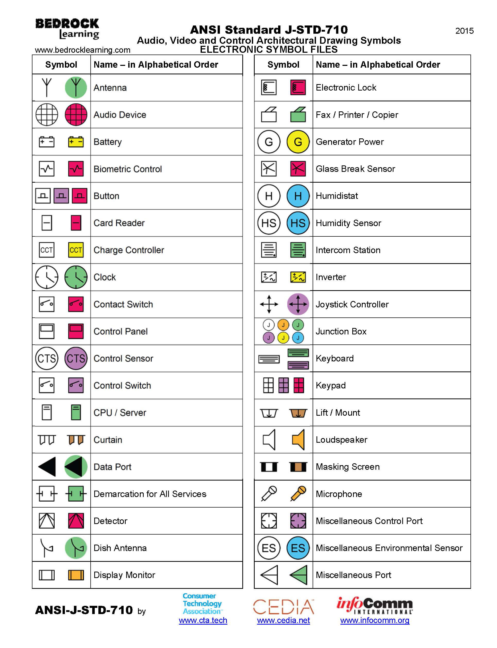
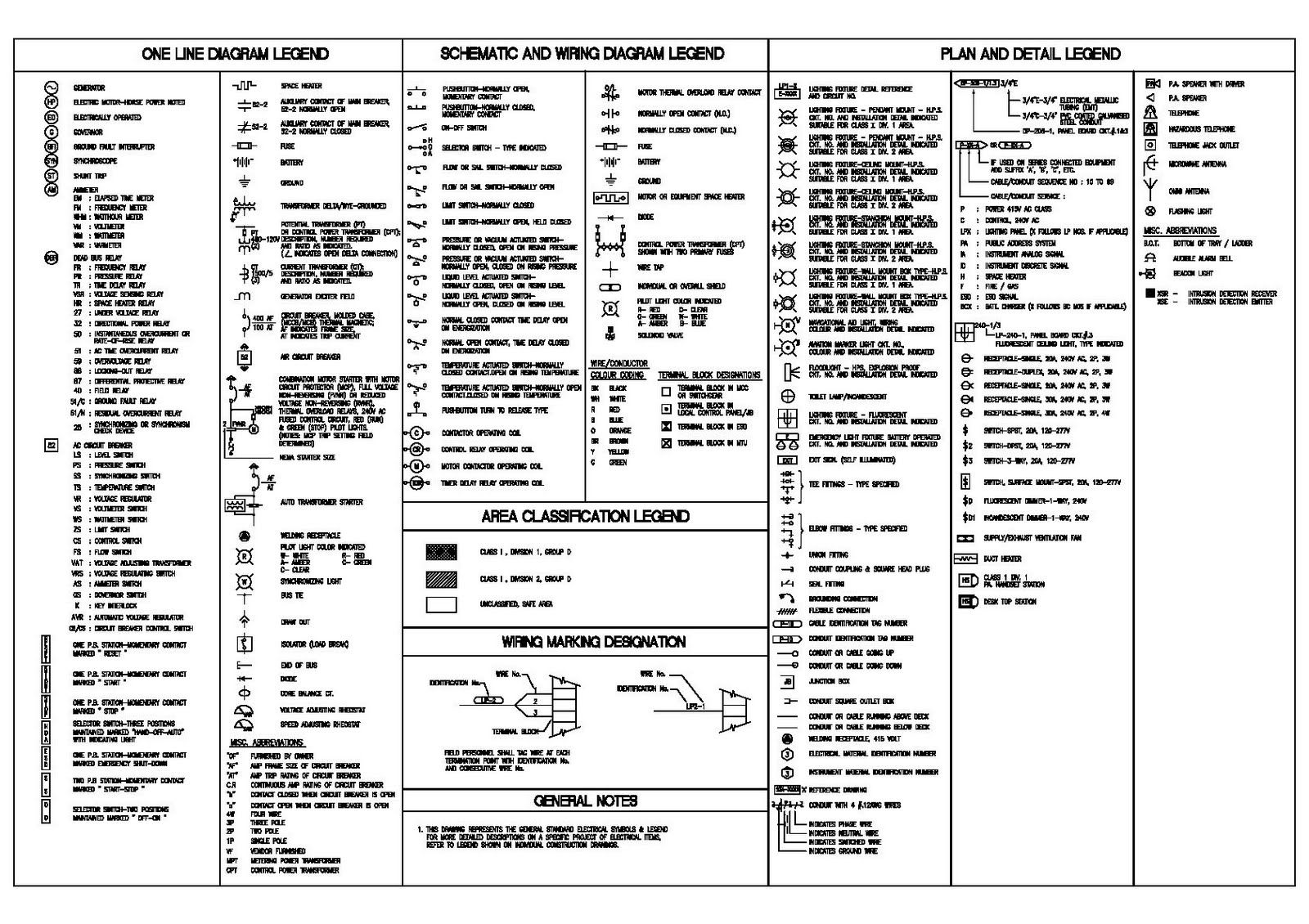
ANSI Standard JSTD710 Architectural Drawing Symbols Bedrock Learning

Mechanical Engineering Drawing Symbols Pdf Free Download at
Engineering Drawing Symbols And Their Meanings Pdf at PaintingValley

Engineering Drawing Symbols And Their Meanings Pdf at PaintingValley
Web Engineering Citation Styles.
Web For Example, Engineering Symbols Are Used In Technical Drawings To Convey The Specific Geometry And Other Details About Pieces Of Equipment Or Components.
Most Symbols Have Been In Y14.5 Since At Least 1994.
Engineering Graphics Is Used In The Design Process For Visualization, Communication, And Documentation.
Related Post:
