Draw The Shear And Moment Diagrams For The Beam Shown
Draw The Shear And Moment Diagrams For The Beam Shown - Civil engineering questions and answers. Once these are determined, derive the shear and moment functions. P р a a l prob. Draw the shear and moment diagrams for the beam shown below. Web the first step in calculating these quantities and their spatial variation consists of constructing shear and bending moment diagrams, \(v(x)\) and \(m(x)\), which are the internal shearing forces and bending moments induced in. A) determine the reactions at the supports. Our calculator generates the reactions, shear force diagrams (sfd), bending moment diagrams (bmd), deflection, and stress of a cantilever beam or simply supported beam. Web draw the shear force and bending moment diagrams for the beam shown below. Shear and bending moment equations. (45in.) 100 lb(15in.) 250 lb(20 in.) 100 lb(55in.) 0r 200 lbre fryc 0: When x = 10, v=blank 1kn, m=blank 2knm absolute vmax=blank 3kn absolute mmax=blank 4knm round your answers up to 3 decimal places. In general the process goes like this:. (b) set p = 800 lb, a = 5 ft, l = 12 ft. A) determine the reactions at the supports. Web write equations for the shear v and bending moment. You'll get a detailed solution from a subject matter. (9) 9 × 0 2 3 ∴ r = 9 kn. 5/117 draw the shear and moment diagrams for the beam shown. We go through breaking a beam into. P1 = 30k w1 = 3k/ft p2 = 2k w2 = 300 lbs/ft. In each problem, let x be the distance measured from left end of the beam. Web calculate shear force diagrams. Mechanical engineering questions and answers. We go through breaking a beam into. Write shear and moment equations for the beams in the following problems. The support at a is a roller and the support at b is a pin. Write shear and moment equations for the beams in the following problems. Web below is a simple example of what shear and moment diagrams look like, afterwards, the relation between the load on the beam and the diagrams will be discussed. P р a a. Also, draw shear and moment diagrams, specifying values at all change of loading positions and at points of zero shear. The shear force and bending moment diagrams are convenient visual references to the internal forces in a beam; How to use skyciv beam calculator. Web draw the shear and moment diagrams for the beam shown. − 6 × 9 1. (9) 9 × 0 2 3 ∴ r = 9 kn. In general the process goes like this:. Also, draw shear and moment diagrams, specifying values at all change of loading positions and at points of zero shear. You'll get a detailed solution from a subject matter. Web shear and moment equations and diagrams for beams. Web below is a simple example of what shear and moment diagrams look like, afterwards, the relation between the load on the beam and the diagrams will be discussed. Web the first step in calculating these quantities and their spatial variation consists of constructing shear and bending moment diagrams, \(v(x)\) and \(m(x)\), which are the internal shearing forces and bending. Web shear and moment equations and diagrams for beams. This problem has been solved! The reactions shown on the diagram are determined from equilibrium equations as follows: Welcome to our free beam calculator! Figures 1 through 32 provide a series of shear and moment diagrams with accompanying formulas for design of beams under various static loading conditions. In general the process goes like this:. (45in.) 100 lb(15in.) 250 lb(20 in.) 100 lb(55in.) 0r 200 lbre fryc 0: Web draw the shear and moment diagrams for the beam (a) in terms of the parameters shown; Web determine the reactions and draw the shear and moment diagrams for the beams shown below. 90k views 3 years ago statics. When x = 10, v=blank 1kn, m=blank 2knm absolute vmax=blank 3kn absolute mmax=blank 4knm round your answers up to 3 decimal places. Mechanical engineering questions and answers. To create the shear force diagram, we will use the following process. Our calculator generates the reactions, shear force diagrams (sfd), bending moment diagrams (bmd), deflection, and stress of a cantilever beam or. Draw the shear and moment diagrams for the beam shown below. The beginning, end, or change of a load pattern. The shear force and bending moment diagrams are convenient visual references to the internal forces in a beam; Web below is a simple example of what shear and moment diagrams look like, afterwards, the relation between the load on the beam and the diagrams will be discussed. Also, draw shear and moment diagrams, specifying values at all change of loading positions and at points of zero shear. Web draw the shear and moment diagrams for the beam, and determine the shear and moment throughout the beam as functions of x. Web by plotting these expressions to scale, obtain the shear force and bending moment diagrams for the beam. Web write equations for the shear v and bending moment m for any section of the beam in the interval ab. Leave all distributed forces as distributed forces and do not replace them with the equivalent point load. Neglect the mass of the beam in each problem. To create the shear force diagram, we will use the following process. The support at a is a roller and the support at b is a pin. Web draw the shear and moment diagrams for the beam shown. The reactions shown on the diagram are determined from equilibrium equations as follows: Draw out a free body diagram of the body horizontally. Web calculate shear force diagrams.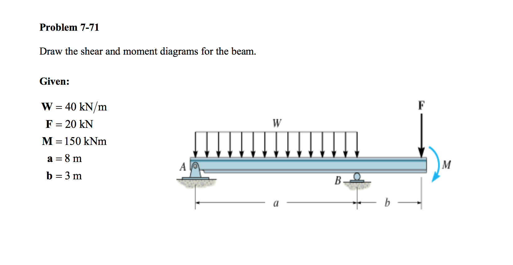
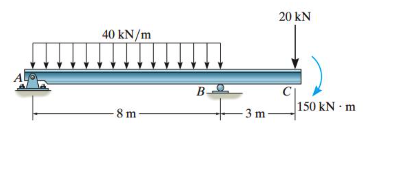
Solved Draw the shear and moment diagrams for the beam.

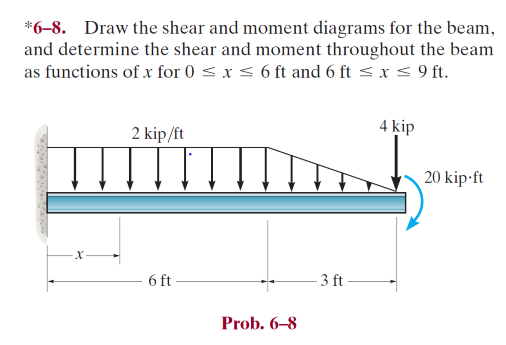
Solved Draw the shear and moment diagrams for the beam, and
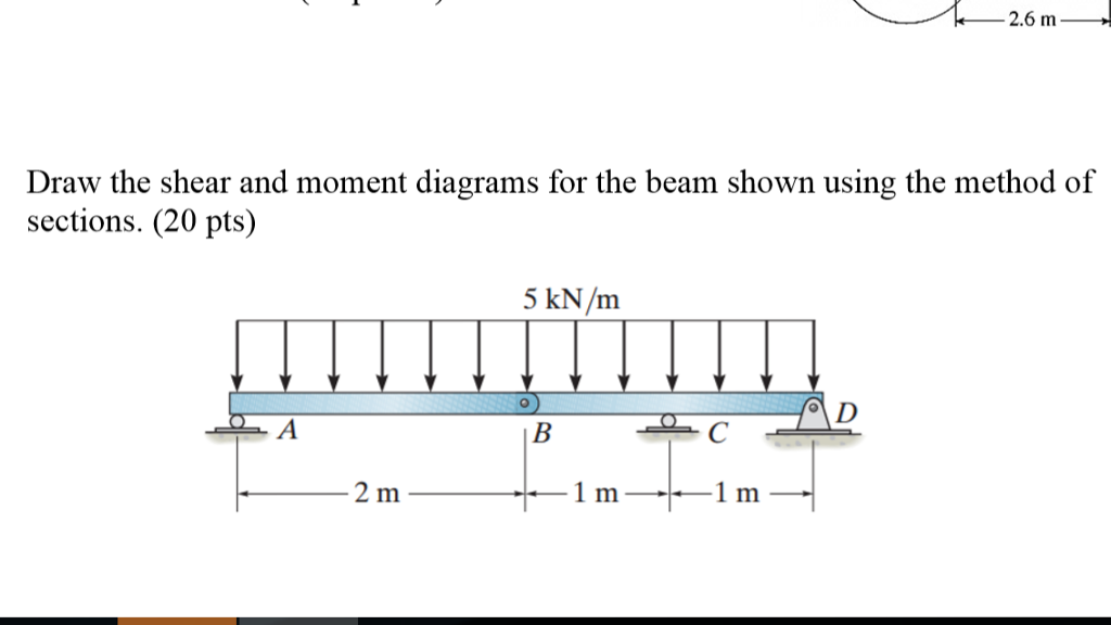
Solved Draw the shear and moment diagrams for the beam using
Solved Draw The Shear And Moment Diagrams For The Beam, A...

Learn How To Draw Shear Force And Bending Moment Diagrams Engineering
Solved Draw the shear and moment diagrams for the beam

Solved Draw the shear and moment diagrams for the beam.

Solved Draw the shear and moment diagrams for the beam (a)
Solved Draw The Shear And Moment Diagrams For The Beam Sh...
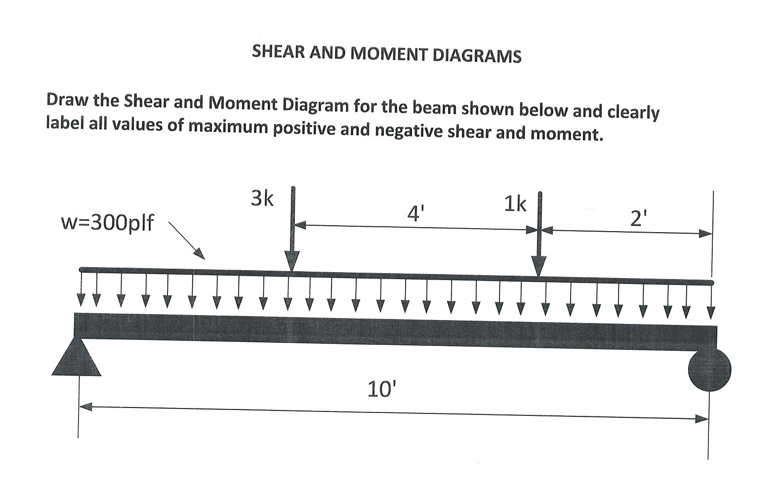
Solved Draw the Shear and Moment Diagram for the beam shown
Web Draw The Shear Force And Bending Moment Diagrams For The Beam Shown Below.
In Particular, They Identify The Maximum Values Of V And M.
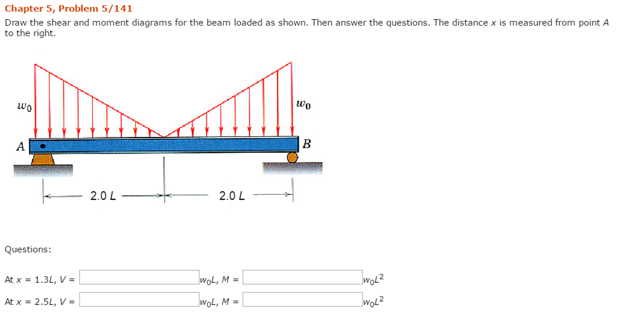
Draw The Shear And Moment Diagrams For The Beam Shown Below Using The Section Cut Method.
Determine The Shear And Moment At X=2 Ft And At X=6 Ft.
Related Post: