Dimension Rules In Engineering Drawing
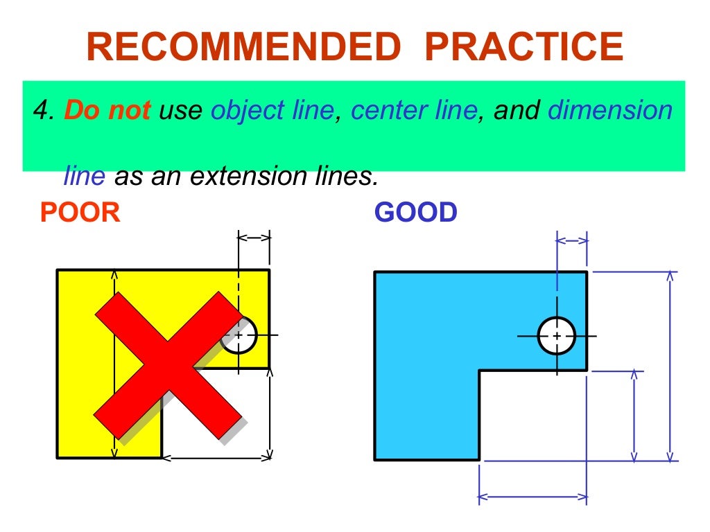
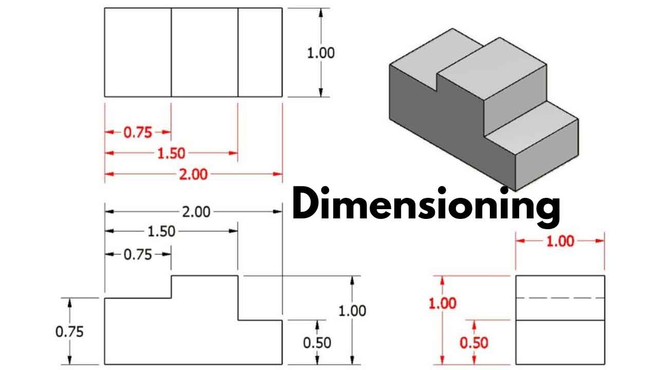
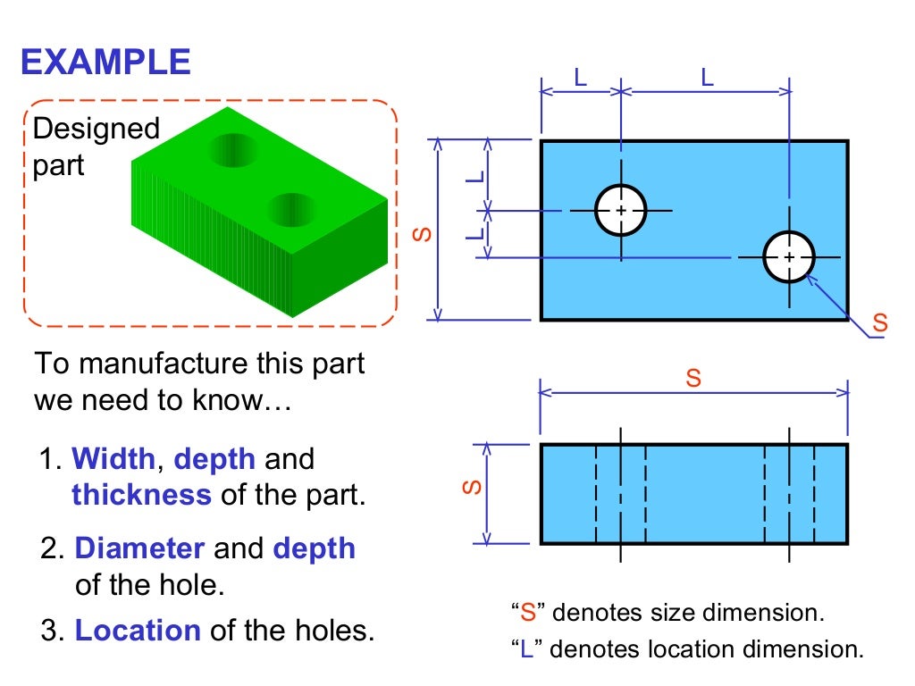
Dimension Rules In Engineering Drawing - It then covers components of dimensioning like extension lines, dimension lines, leader lines and. Property indicators (symbols) rules for dimensioning. Basic components of an engineering drawing. Dimensioning should follow these guidelines. Dimensions must be placed in appropriate positions. Web the common metric unit of measure on engineering drawings is the millimeter, abbreviated as mm. What if there was no standard for bolts? These are indicated on the engineering drawing to define the size characteristics such as length, height, breadth, diameter, radius, angle, etc. Tolerances may be applied directly to size dimensions. We are going to look at what dimensioning is, what are the elements of the dimensions and what the rules for. Tolerances shall be applied using feature control frames when feature definition is basic. On a multiview drawing, dimensions should generally be placed between adjacent views. What if there was no standard for bolts? 23k views 3 years ago engineering drawing and it's basics. Each feature shall be toleranced. Do not leave any size, shape, or material in doubt. Web dimensions in engineering drawings are numerical values indicated graphically in a proper unit of measurement on engineering drawing with lines, symbols, and notes. Tolerances shall be applied using feature control frames when feature definition is basic. Web in this video, we are going to learn about dimensions in engineering. Geometrics is the science of specifying and tolerancing the shapes and locations of features on objects. On a multiview drawing, dimensions should generally be placed between adjacent views. A complete set of dimensions will permit only one interpretation needed to construct the part. Dimensions and notations must be placed on the sketch where they can be clearly and easily read.. This youtube channel is dedicated to teaching people how to improve their technical. Web additional and more specific rules and details about the use of dimensioning for construction engineering are given in iso 6284. Each feature shall be toleranced. Web to ensure that engineering drawings are dimensioned correctly, various industry standards must be followed. Dimension this three inch cube. Web sometime space and time is limited and you might have to bend the typical rules of drawing and dimensioning. Web to ensure that engineering drawings are dimensioned correctly, various industry standards must be followed. Web best practice 2. What if there was no standard for bolts? Extension line, dimension line, nominal value, and terminator. Web the process of adding size information to a drawing is known as dimensioning the drawing. Dimensions should not be duplicated or the same information given in two different ways (dual dimensioning excluded). Web it establishes symbols, rules, definitions, requirements, defaults, and recommended practices for stating and interpreting gd&t and related requirements for use on engineering drawings, models defined in. Let’s see what makes up an engineering drawing. Each dimension should be given clearly so it can be interpreted in only one way. Property indicators (symbols) rules for dimensioning. 23k views 3 years ago engineering drawing and it's basics. Web sometime space and time is limited and you might have to bend the typical rules of drawing and dimensioning. Web best practice 2. So let’s take a closer look. Web fundamentals of dimensioning rules. Basic components of an engineering drawing. Web this document discusses dimensioning practices for engineering drawings. 23k views 3 years ago engineering drawing and it's basics. These are indicated on the engineering drawing to define the size characteristics such as length, height, breadth, diameter, radius, angle, etc. Web the general guideline is that each dimension should be placed on the view which shows the dimensioned feature most clearly, and which gives the clearest and least cluttered. Basic components of an engineering drawing. Property indicators (symbols) rules for dimensioning. Web all you need to do is add the dimensions. Web the process of adding size information to a drawing is known as dimensioning the drawing. Having models also makes updating the drawings for revisions simple. Web the common metric unit of measure on engineering drawings is the millimeter, abbreviated as mm. It then covers components of dimensioning like extension lines, dimension lines, leader lines and. So let’s take a closer look. Web it establishes symbols, rules, definitions, requirements, defaults, and recommended practices for stating and interpreting gd&t and related requirements for use on engineering drawings, models defined in digital data files, and in related documents. Dimensions should be added to the view which shows the shape of the part clearly. Basic components of an engineering drawing. Tolerances may be applied directly to size dimensions. The rules that are relevant to interpreting basic to intermediate engineering drawing dimensions are explained. Web the purpose of dimensioning is to provide a clear and complete description of an object. Extension line, dimension line, nominal value, and terminator. Do not leave any size, shape, or material in doubt. Also, add dimensions with the correct scale so that no scale conversion is required to infer the dimension. Having models also makes updating the drawings for revisions simple. Each dimension should be given clearly so it can be interpreted in only one way. On a multiview drawing, dimensions should generally be placed between adjacent views. Correct values must be given.
Dimensioning Rules in Engineering Drawings YouTube

Dimensioning Rules YouTube

GENERAL RULES OF DIMENSIONING in Engineering Drawing YouTube
Dimensioning rules in engineering drawing
TECHNICAL MODELS AND ARTS BASICS IN DIMENSIONING
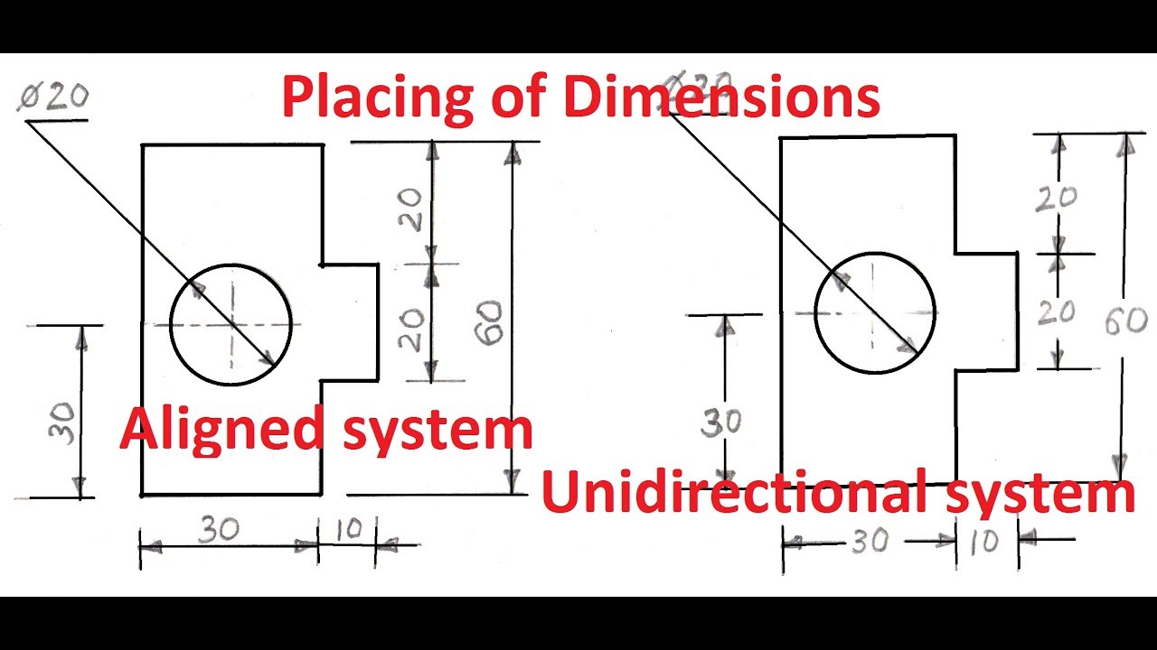
1.4aPlacing of Dimension Systems in Engineering Drawing Aligned and

Rules For Dimensioning Mechanical Drawings YouTube
Dimensioning rules in engineering drawing
PPT A Brief Introduction to Engineering Graphics PowerPoint
![Dimension rules in Engineering Drawing/Graphics [G01] Introduction](https://i.ytimg.com/vi/nHWP91huUW4/maxresdefault.jpg)
Dimension rules in Engineering Drawing/Graphics [G01] Introduction
A Single Drawing Includes Many Elements With Quite A Few Variations To Each Of Them.
Sometimes, You Will Have To Place Dimensions In Two Units Simultaneously!
23K Views 3 Years Ago Engineering Drawing And It's Basics.
Web Learn The Fundamental Rules Of Dimensioning In Engineering/Architectural/Structural Drawings.
Related Post: