Center Line Drawing
Center Line Drawing - Select two points to position the centerline. Web published on may 01, 2024. Web structural lines and center lines are a key part of the sketching process for both traditional animation and standard drawing and are used to help create balanced, symmetrical figures with proper distribution of weight and perspective views. They are also used to indicate circle of centers and paths of motion. Center lines are an important element of engineering drawings that are used to represent the axis of symmetry for a part or assembly. Center lines can show the position of related holes or or other cylindrical elements. Center lines are thin, alternating long and short dashes that are generally used to show hole centers and center positions of rounded features, such as arcs and radii. These lines are drawn as long, thin dashed lines and are used to indicate the center point of cylindrical features, such as holes or shafts. Web centerlines are annotations that mark circle centers and describe the geometry size on drawings. Web you can add center lines and symmetry lines to your drawing. A centerline is a type of construction geometry. This is not all there is. Web the standard line types used in technical drawings are center lines are used: Web centerlines are annotations that mark circle centers and describe the geometry size on drawings. Web published on may 01, 2024. For each point, select an arc or circle at the point of tangency. Web centerlines are annotations that mark circle centers and describe the geometry size on drawings. Leader lines are used to direct attention to specific areas or features on an engineering drawing. Center lines are an important element of engineering drawings that are used to represent the axis. You can insert centerlines into drawing views automatically or manually. Set styles for these marks, and add the center of gravity mark for a model. To represent symmetry, to represent paths of motion, to mark the centers of circles and the axes of symmetrical parts, such as cylinders and bolts. You can select multiple center marks in a drawing and. They are typically utilized when pointing to notes, labels, or callouts that provide additional information about a particular object or detail. In a layout, on the design tab, select one of the following: In order to print an image that started as a color photo, it needs to be converted into a black and white line drawing, or “sketch.” You. They are also used to indicate circle of centers and paths of motion. Molten at the kavanagh gallery. Their basic purpose is to show circular/cylindrical features in a drawing, which are found in abundance in mechanical parts. Web the center line aids in achieving balance, alignment, and alignment in the construction or manufacturing process. Web structural lines and center lines. Web centerlines on engineering drawings and how they should be used correctly. To create a center line, this command allows you to create a center line for a circular element. Center lines may be connected within a single view to show that two or more features lie in the. You can insert centerlines into drawing views automatically or manually. A. Leader lines are used to direct attention to specific areas or features on an engineering drawing. Center lines are thin, alternating long and short dashes that are generally used to show hole centers and center positions of rounded features, such as arcs and radii. Cnc machining allows centerline to reduce your lead time to as little as one day. Web. Web centerlines are annotations that mark circle centers and describe the geometry size on drawings. 13k views 3 years ago print reading &. Center lines denote a circular feature such as a shaft or a hole. The proportion once selected should be maintained throughout the drawing. Center lines should extend a short distance beyond the object or feature. The solidworks software avoids duplicate centerlines. Parent topic center marks and centerlines. Center lines may be connected within a single view to show that two or more features lie in the. Web the standard line types used in technical drawings are center lines are used: To represent symmetry, to represent paths of motion, to mark the centers of circles and. Web centre lines, lines of symmetry, trajectories, and pitch circles type of lines are long, thin, chain lines with alternately long and short dashes of proportion ranging from 6:1 to 4:1 and evenly spaced. These are useful for aligning elements and when adding dimensioning parameters. Web centerlines on engineering drawings and how they should be used correctly. Molten at the. Add these automatically or manually to holes, arcs, and other features; 13k views 3 years ago print reading &. Center lines represent axes of symmetry and are important for interpreting cylindrical shapes. The proportion once selected should be maintained throughout the drawing. Web centerlines on engineering drawings and how they should be used correctly. To represent symmetry, to represent paths of motion, to mark the centers of circles and the axes of symmetrical parts, such as cylinders and bolts. You can select multiple center marks in a drawing and align them to a selected edge or geometry. Web onverting images from color photos to line drawings is a great tool to use for the laser utter. Center lines can show the position of related holes or or other cylindrical elements. Set styles for these marks, and add the center of gravity mark for a model. Web the standard line types used in technical drawings are center lines are used: These are useful for aligning elements and when adding dimensioning parameters. You can use centerlines to define a line of symmetry or an axis with a sketch. Model making requires experience in a wide array of techniques and fields. Click centerline and select two points to position the centerline. You can create centerlines in a sketch and then use the centerlines when you create entities in part or assembly mode.
Center line plan of residence ground floor plan centerlineplan
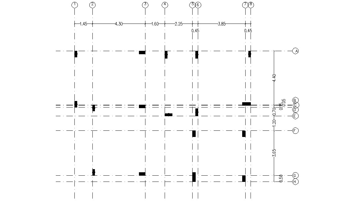
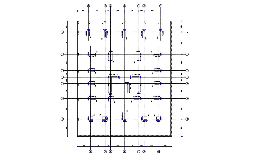
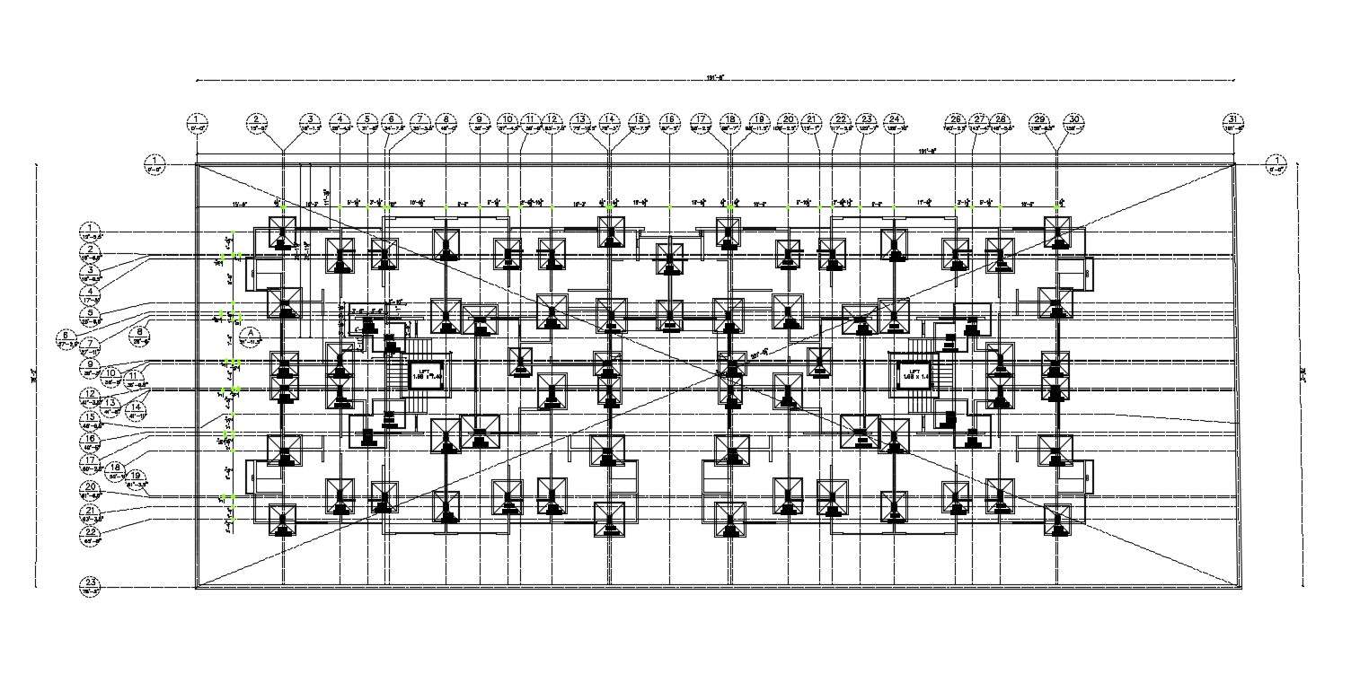
Simple Column Plan With Centre Line CAD Drawing Cadbull
Free Download Column Center Line Plan Design DWG File Cadbull
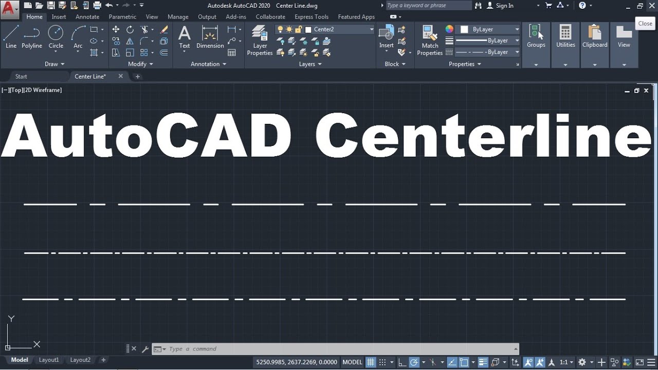
How to Draw Center line in AutoCAD YouTube
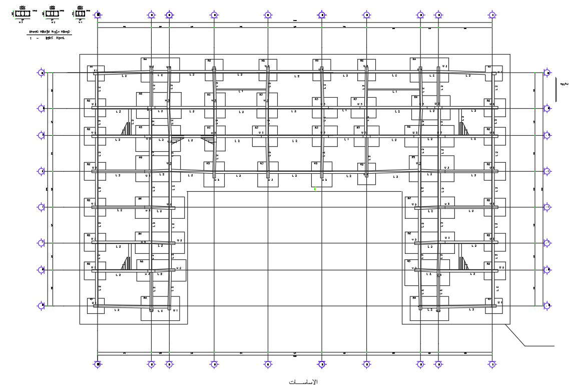
2D CAD Drawing Centre Line Plan And Foundation Plan Free Download Cadbull

2020 Drawing Center Lines for an Orthographic Drawing YouTube
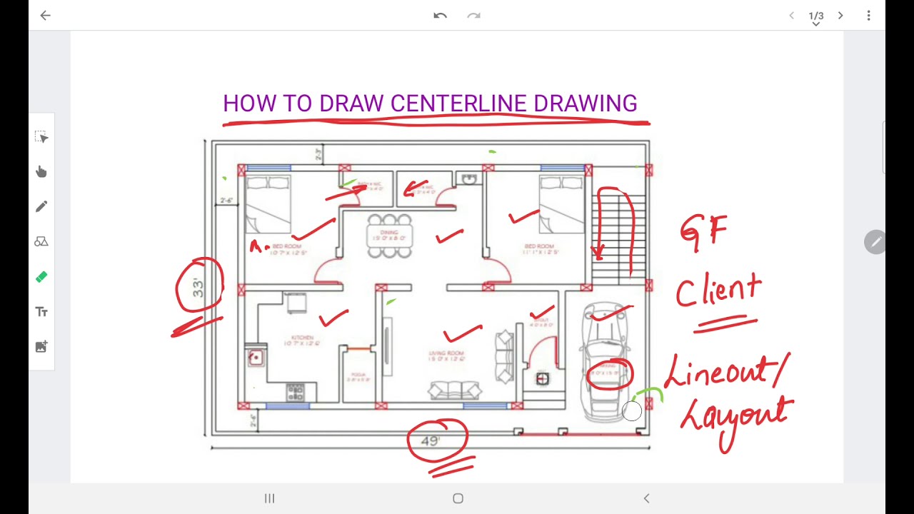
HOW TO PREPARE CENTERLINE DRAWING YouTube
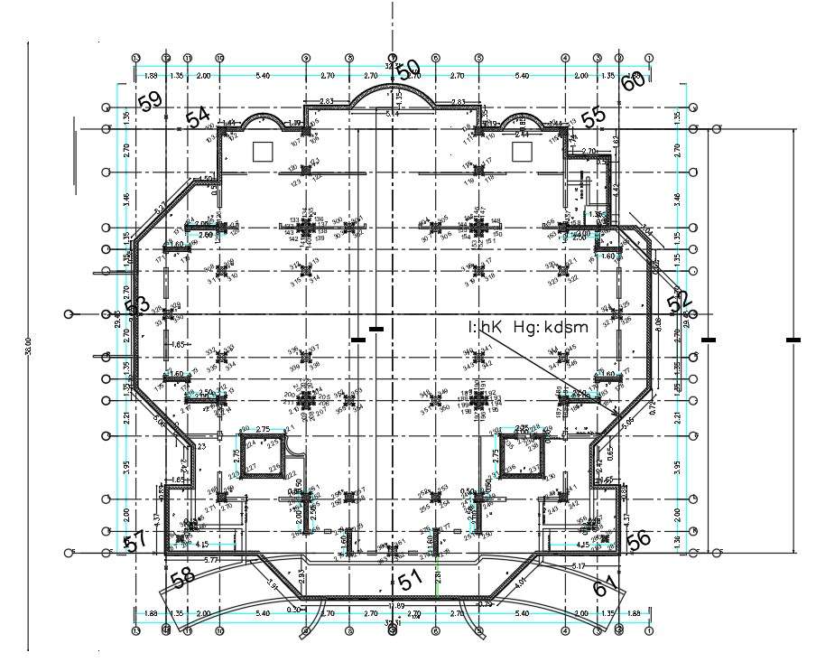
Architecture Building Center Line Plan CAD Drawing DWG File Cadbull
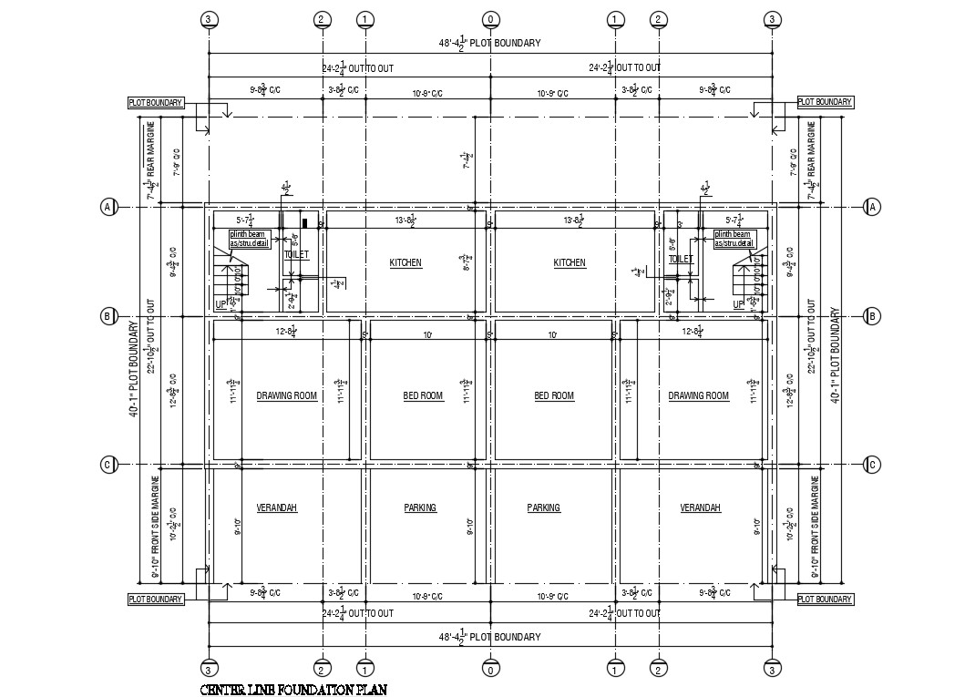
Center Line Foundation Plan Of House Drawing AutoCAD File Cadbull
Center Line Plan And Foundation Plan Detail Drawing Free File Cadbull
Center Lines May Be Connected Within A Single View To Show That Two Or More Features Lie In The.
The Solidworks Software Avoids Duplicate Centerlines.
They Are Typically Utilized When Pointing To Notes, Labels, Or Callouts That Provide Additional Information About A Particular Object Or Detail.
Center Lines Denote A Circular Feature Such As A Shaft Or A Hole.
Related Post: