Camshaft Drawing
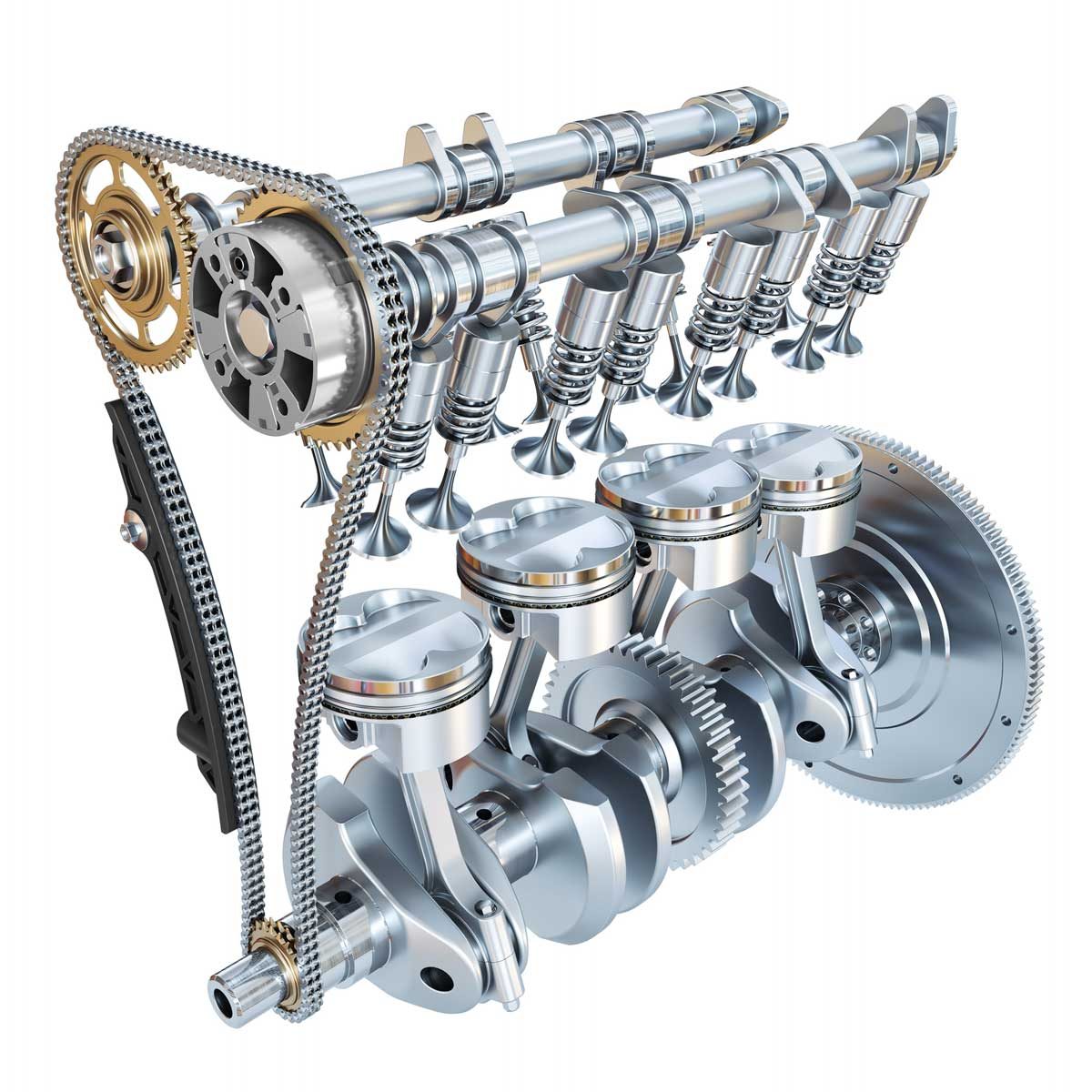
Camshaft Drawing - Web draw the circle equal to the diameter of the shaft or give the dimension constraints using smart dimensions. They're driven by a belt or a chain,. Web basic camshaft understanding discussing lift, duration, degrees, overlap, dialing in cam timing, and grinds for max power and fuel efficiency and torque Join the grabcad community today to gain access and download! Is used by many companies around the world to design commercial cams and is available in two versions. In direction 1 select the midplane option, give the length value and click ok. The work is done by students in graphical communication & spatial analysis. In the cam design and calculation dialog box, define the cam mechanism in the following sequence: Go to the features tab and click on the extrude boss/base. Web the cam profile is the actual shape of the camshaft lobe. To picture cam lobe separation a little better, look at the end of a traditional v8 camshaft. Go to the features tab and click on the extrude boss/base. Once the cam profiles are designed, the next step is to make the camshaft. This video focuses on how to draw a cam profile. If you’re interested in engineering and designing mechanical. January 9, 2023 by saif m. Obviously, making the camshaft is much more involved. The work is done by students in graphical communication & spatial analysis. 546k views 6 years ago cam profile. Web how to draw displacement diagrams for simple harmonic motion and how to draw cam profiles for knife edge follower, roller follower, and flat face followers. A flat tappet camshaft is slightly more pointed on the nose of the lobe, while a roller lift camshaft has a more rounded profile on the nose of the lobe. In the cam design and calculation dialog box, define the cam mechanism in the following sequence: This video focuses on how to draw a cam profile. Join the grabcad community. 546k views 6 years ago cam profile. In the cam design and calculation dialog box, define the cam mechanism in the following sequence: The crankshaft is a shaft used to convert the reciprocating or oscillating motion of a piston into a rotary motion. The content was based on a question extracted from a past exam paper for mechanical draughting n4.. Drawing accurate cam profiles is crucial for ensuring optimal performance and efficiency of machines. & return stroke is with uniform velocity.a fully animated cam prof. & uniform acceleration & retardation. There are many stages in the camshaft manufacturing process. The most misunderstood component of an engine is the camshaft. And its types, nomenclature, working, application, and more with diagrams. Yet, the camshaft has a major impact on engine performance. Definition, types, working & uses [pdf] last updated on: Ezcam with a custom 60 mm camshaft. Obviously, making the camshaft is much more involved. Definition, types, working & uses [pdf] last updated on: 172k views 7 years ago cam profile. A flat tappet camshaft is slightly more pointed on the nose of the lobe, while a roller lift camshaft has a more rounded profile on the nose of the lobe. This video focuses on how to draw a cam profile. Join the grabcad community. This is a process that synchronizes the camshaft with the crankshaft. Yet, the camshaft has a major impact on engine performance. It has been completely rewritten to be compatible with windows 10. Web the cam calculation feature is used to design cam profiles for linear, circular, or cylindrical cams. Is used by many companies around the world to design commercial. Web the video shows the projection and isometric drawing of a camshaft using autocad. It has been completely rewritten to be compatible with windows 10. Working of valves in an internal combustion engine is controlled by camshaft. 172k views 7 years ago cam profile. The most misunderstood component of an engine is the camshaft. In direction 1 select the midplane option, give the length value and click ok. Web how to draw displacement diagrams for simple harmonic motion and how to draw cam profiles for knife edge follower, roller follower, and flat face followers. The grabcad library offers millions of free cad designs, cad files, and 3d models. In the cam design and calculation. Web draw the circle equal to the diameter of the shaft or give the dimension constraints using smart dimensions. In the cam design and calculation dialog box, define the cam mechanism in the following sequence: A cam is a mechanical component used to convert rotational motion into linear motion. Once the cam profiles are designed, the next step is to make the camshaft. The size of the base circle is Web home » mechanical engineering » cam and follower: Working of valves in an internal combustion engine is controlled by camshaft. To picture cam lobe separation a little better, look at the end of a traditional v8 camshaft. 18k views 2 years ago. In direction 1 select the midplane option, give the length value and click ok. Obviously, making the camshaft is much more involved. The smallest circle centered on the cam rotation axis, and tangent to the cam surface. Ezcam with a custom 60 mm camshaft. This video explains how to draw displacement diagram in case of follower motion with s.h.m. 546k views 6 years ago cam profile. Join the grabcad community today to gain access and download!
How to Design Cam Shaft (6 profile ) 210 Industrial design

How to design a Camshaft V12 Engine Design & Assembly 6 Autodesk
Camshafts And Valves Working And Classification!

INCH Technical English pictorial camshaft

AutoCAD 3D Modeling 8 Cam shaft By (ⓐⓤⓣⓞⓒⓐⓓⓒⓜⓓ) YouTube
Camshaft Detail Drawing W1 PDF
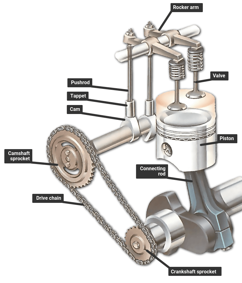
Camshaft with pushrods

James Hough Camshaft

Camshaft Types, Functions & Examples StudiousGuy
![Camshaft Working and Types Details] Engineering Learn](https://engineeringlearn.com/wp-content/uploads/2021/01/Camshaft-scaled-e1611558388433.jpg)
Camshaft Working and Types Details] Engineering Learn
A Shaft With One Or More Cams Attached To It, E.g.
Web This Video Explains How To Draw Cam Profile When Out Stroke Of The Follower Is With S.h.m.
Go To The Features Tab And Click On The Extrude Boss/Base.
And Its Types, Nomenclature, Working, Application, And More With Diagrams.
Related Post:
